Worked Example: Automatic Design of Timber Connections
1. About this article
This article explains the automatic timber connection design of StatiCAD from start to finish in a two-storey timber building with screenshots: opening the project and the analysis, finding the connections automatically from the model, designing the screwed connection, reading the result list, interpreting unsuitable connections, the effect of the options, detail drawings, the calculation report and verifying a connection by hand. All values are the real inputs of the example building, and all results are the results the program gives in this example.
For all the options and the details of the connection form, see the article Timber Connection Calculations.
Version: Automatic connection design (the Automatically Design Timber Connections command in the plan right-click menu) is available in the StatiCAD Ultimate and Hybrid versions. In the demo version, the calculation report and drawing of only the first 3 detail types (3 connections) are given; the report cannot be written to a file. Automatic design does not change the analysis results and member checks; it only reads them. The screenshots were taken with StatiCAD Ultimate V.10.1.1.0.
Example files: You can download here the project files of the two examples in the article (ZIP):
AhsapBirlesimOrnek.sy4: two-storey timber building (Sections 2–12); AhsapBirlesimKucukOrnek.sy4: small frame with four columns (Section 13, easy to follow by hand). Open the file with File › Open and run the analysis; since the analysis results are not saved in the project file, the analysis must be repeated every time it is opened.
2. Example building
A timber house with a 12.00 × 6.00 m plan, two storeys (BASEMENT and GROUND FLOOR) and a hipped roof. The vertical load-bearing members are timber posts (columns) and timber shear walls at the corners; between the posts on each storey there are five rows of horizontal blocking (22 × 15 cm) at 60 cm spacing. The floors are a timber joist grid (10 × 15 cm) at 60 cm spacing with 2 cm OSB sheathing on top. The roof consists of timber trusses produced with the truss wizard. All members are C24 class timber (ρk = 350 kg/m³).
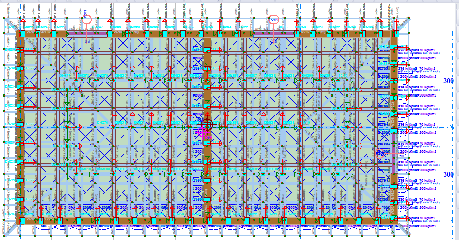
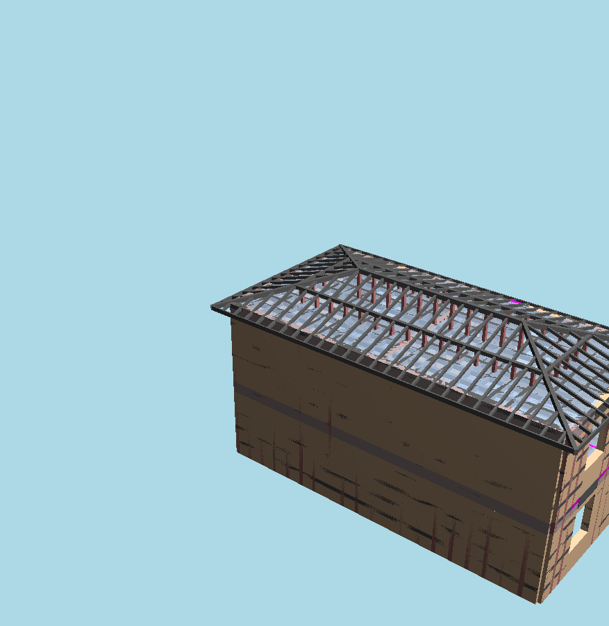
Table 1 – General information
| Item | Value |
|---|---|
| Plan | 12.00 × 6.00 m (x = 300…1500 cm, y = 300…900 cm) |
| Storeys | BASEMENT and GROUND FLOOR; the storey index in member names is B and Z (e.g. HB05 = basement beam no. 5, DHZ12 = ground floor post no. 12) |
| Timber class | C24 (softwood): fm,k = 24 MPa, ρk = 350 kg/m³ |
| Posts (columns) | 15 × 22 cm; storey height, drawn connected to the node by one edge |
| Blocking | 22 × 15 cm horizontal beams; between the posts, at five different levels on each storey |
| Floor joists | 10 × 15 cm; at 60 cm spacing |
| Floor | 2 cm OSB sheathing, Gsheathing = 20 kg/m², Q = 200 kg/m² |
| Timber shear walls | 8 on each storey, 24 cm thick, 1.50 m long |
| Load combinations | User-defined combinations are selected in the project (1.35Gk+1.5Qk, combinations with wind and with earthquake). The governing ones among the connections: 1.35Gk+1.5Qk (974), Gk+Qk+0.4Sk+Ex2+0.3Ey1+0.3Edz (163), Gk+Qk+0.4Sk-Ey1-0.3Ex2+0.3Edz (153), Gk+Qk+0.4Sk+Ex1-0.3Ey1+0.3Edz (118) |
| Moisture factor CN | each member's own selection (Beam / Column Properties); in the connections in this model 0.95 (648 connections), 0.85 (1332 connections) |
Table 2 – Connections the program finds in this model
| Type | Number | Description |
|---|---|---|
| Beam-to-beam (T) | 708 | Ends where a beam runs into the side face of another beam |
| Beam-to-column | 1374 | Ends where blocking and floor joists are connected to the posts |
| Bearing on wall | 24 | Beam ends sitting on a timber shear wall (outside the scope of screwed design) |
| End-to-end (corner / splice) | 6 | Corners where two beam ends meet at the same point and splices of beams continuing in their own direction (outside the scope) |
| Total | 2112 | 1980 of them were designed; beams not scanned because they are inclined beams / truss members: 258 |
3. Summary of the connection design
The program connects the end of the secondary (carried) beam to the side face of the main member (beam or column) it runs into with fully threaded screws. The screws are driven inclined in the vertical plane through the axis of the secondary beam so as to make an angle θ with the horizontal, and work axially; the shear force of the connection is carried by the vertical component of the axial forces of the screws.
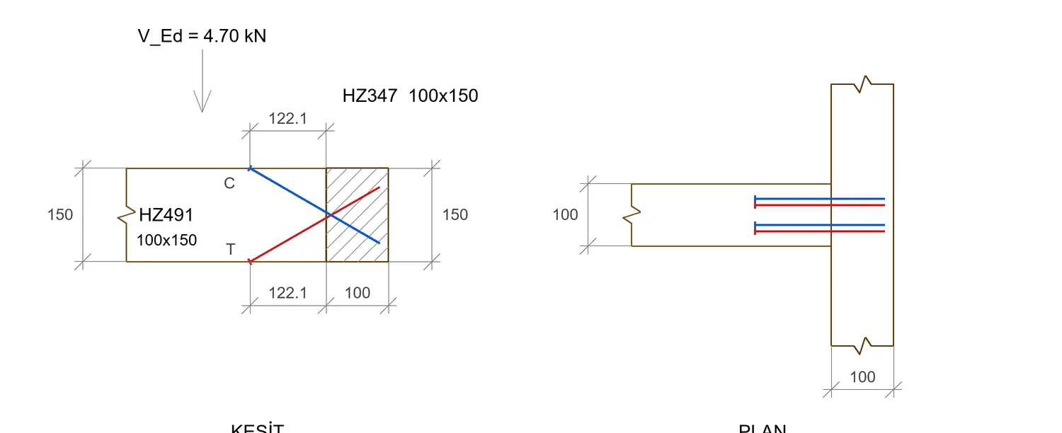
Figure 3 – Crossed screw pair: the tension screw T enters from the bottom face of the secondary beam and rises towards the main member, the compression screw C enters from the top face and descends
Table 3 – Screw arrangements
| Arrangement | Mode of action | Shear capacity |
|---|---|---|
| Crossed screw pair | In each pair, one screw works in tension (T), the other in compression (C). It also works under load reversal; this arrangement is tried first in the Automatic option. | VRd = nef · 2 · min(FRd,T; FRd,C) · sin θ (n = number of pairs; the pair is limited by the weaker screw) |
| Inclined (tension-only) screw | All screws work in tension; the horizontal component is resisted by contact at the interface. Tried if no suitable solution is found with the crossed arrangement. | VRd = nef · FRd,T · sin θ (n = number of screws) |
Table 4 – Conditions checked
| Condition | Relation | Basis |
|---|---|---|
| Withdrawal strength of the threaded part (in both members) | fax,k = 0.52 · d−0.5 · lef−0.1 · ρk0.8; Fax,α,Rk = fax,k · d · lef · kd / (1.2 cos²α + sin²α), kd = min(d/8; 1) | Eq. 4.263, 4.264 |
| Head embedment (tension screw) | Fhead,Rk = fhead,k · dh² · (ρk/ρa)0.8; on the head side, the larger of this and the strength of the threaded part is taken | Eq. 4.265 |
| Screw tensile strength | Ft,Rd = ftens,k / γM2 | Eq. 4.266 |
| Effective number of screws | nef = n0.9 | Eq. 4.267 |
| Lateral shear V3 (perpendicular to the beam axis, horizontal) | The screws are loaded laterally: Fv,Rk with Johansen relations (single shear plane, def = 1.1 d1, rope effect not taken); V3,Rd = nef · ΣFv,Rd; interaction with vertical shear η = √(ηV² + η3²) ≤ 1; if η3 > 0.10, loaded edge distance a4,t in the secondary beam (def < 5 mm: 7 def, otherwise 10 def) | EN 1995-1-1, 8.2.2, 8.7.1, Eq. 8.28; Table 4.22 |
| Buckling of the compression screw (additional check) | Nki = √(ch Es Is), λ = √(Npl/Nki), Fki,Rd = κc Npl / γM1 | beam on elastic foundation |
| Tension perpendicular to the grain in the main beam (splitting) | F90,Rk = 14 · b · w · √(he / (1 − he/h)); Fv,Ed = total shear of the beams running into the same section | EN 1995-1-1, 8.1.4 |
| Geometry conditions | a2 ≥ 5d; in the main beam in the grain direction a1 ≥ 7d; a2,CG ≥ 4d; a1,CG ≥ 10d; lef ≥ 6d; t ≥ 12d; 6 ≤ d ≤ 12 mm; θ ≥ 30° | Table 4.24 |
Source of the inputs. The design shear VEd is the support shear at that end of the beam (analysis result, V2; the value of the combination governing in the member check). kmod = cy · CN is taken: cy is the load duration factor of the governing combination, CN is the moisture factor of the member (the smaller of the secondary beam and the main member); the timber member checks use the same factors. ρk and the sections are read from the members, the elevation differences from the model. The screw properties are a generic fully threaded carbon steel screw assumption (d1 = 0.65 d, dh = 1.8 d, ftens,k = 800 MPa × root area, fhead,k = 10 MPa, fy,k = 1000 MPa).
The same combination. V2 and V3 are taken not from separate envelopes but from the same combination: first the governing combination of V2 (with the V3 in that combination), then the governing combination of V3 (with the V2 in that combination) is checked; each with its own cy factor. The combination governing the design is shown in the list, the breakdown and the report.
Lateral shear. The lateral support shear V3 at that end of the beam is also included in the design. The screws lie in the vertical plane of the beam; since V3 is perpendicular to this plane, it loads the screws laterally (in shear). The lateral strength of a single screw is calculated with the Johansen relations, with the effective diameter derived from the root diameter (def = 1.1 d1) and the lengths of the screw in the two members; since the axial capacity of the screw is reserved for the vertical shear, the rope effect is not taken. The vertical and lateral utilisation ratios are combined quadratically: η = √(ηV² + η3²). The η in the list is this combined ratio.
The cy factor: In the program's own combinations, cy = 0.8 is taken for the vertical load combination and 1.1 for seismic combinations. In user-defined combinations (as in this example), cy comes from the duration of action definition of the last load of the combination: "Instantaneous Action" 1.1; "Medium-Term Action" 0.8; other definitions 0.6. The duration of action of the loads is selected in Load Definitions; in this example, the vertical load combination is calculated with 0.60 and the seismic combinations with 1.10.
The geometry conditions are a hard rule: The program does not select an arrangement that violates the spacing / edge / end distance conditions in order to reach the strength: if the strongest arrangement that complies with the conditions is not enough, the status is Inadequate; if no arrangement fits the section while complying with the conditions, it is Geometry condition.
Screw product: The calculation is made with generic screw properties. In practice it must be verified with the performance declaration (DoP / ETA) values of the selected product and the product-specific minimum spacing conditions.
4. Opening the project and analysis
- Open the file
AhsapBirlesimOrnek.sy4with File › Open. If you are on the start screen, go to the working screen with the Main Screen icon. - Open the analysis window with the Analysis button on the top toolbar and press Start Analysis.
- When the analysis is finished, close the window. The support shears of the timber beams are now in memory.
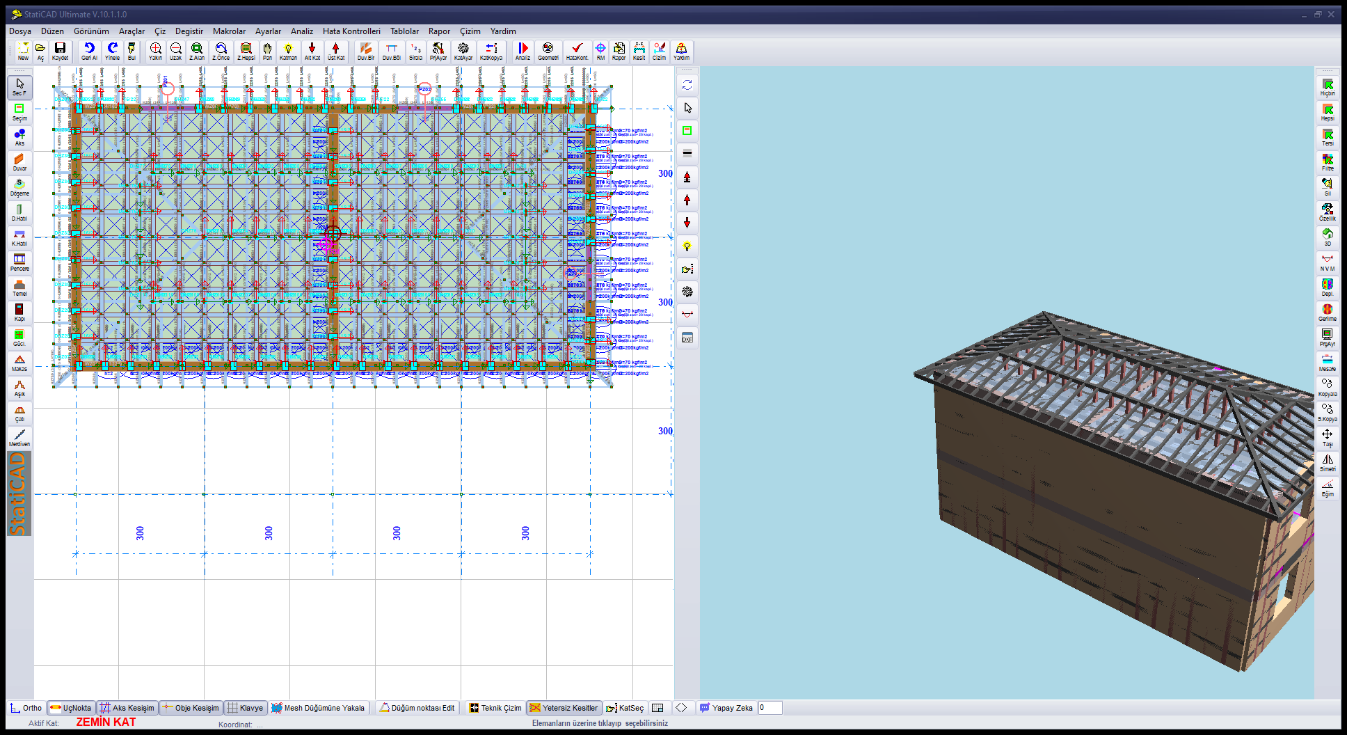
Figure 4 – Main screen after the example project is opened: plan on the left, three-dimensional view on the right
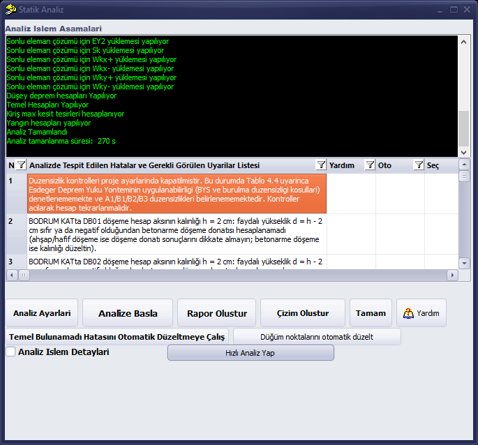
Figure 5 – Analysis window: after the analysis is complete
Does it also work without running the analysis? Yes, but it would not be meaningful: if there is no current analysis result, VEd = 0 is taken, the smallest (constructive) screw arrangement is assigned to each connection, the status becomes No analysis, and the window and the report write this as a WARNING. If the model is changed after the analysis, the analysis is also considered invalid; re-run the analysis.
5. Starting the automatic design
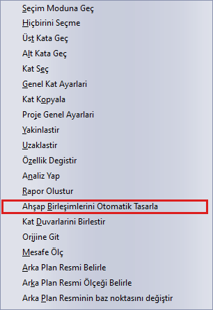
In the plan view, right-click (on an empty area or on a member) and choose Automatically Design Timber Connections from the menu. The command is visible if there is a timber beam in the project; there is no need to select a member.
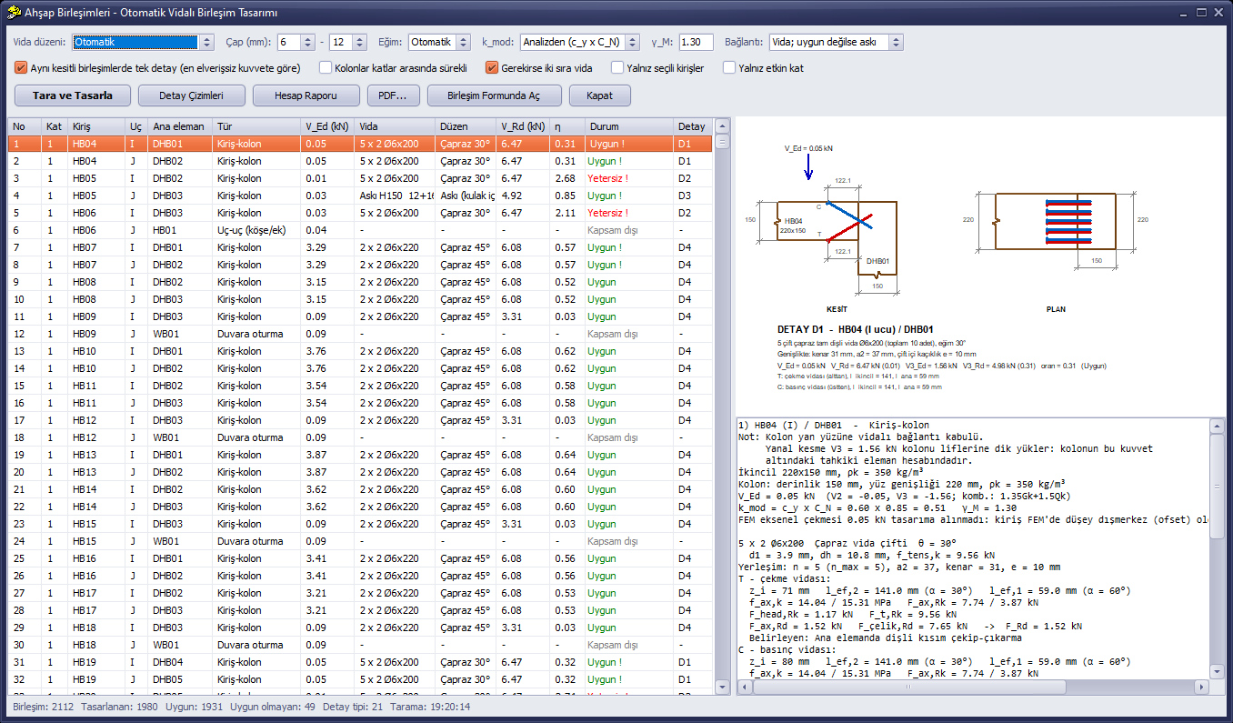
The window scans the model every time it opens and designs all connections. In this example 2112 connections were found, 1980 of them were designed, 1931 of these satisfied all conditions and 49 did not; the designs were collected into 21 detail types (bottom row of the window).
6. Reading the window
6.1 Options

Figure 8 – Options and action buttons
Table 5 – Options
| Option | Default | Description |
|---|---|---|
| Screw arrangement | Automatic | Automatic: first the crossed pair, if there is no suitable solution the inclined screw. If desired, the arrangement is fixed. |
| Diameter (mm) | 6 – 12 | Range of screw diameters to be tried (6, 8, 10, 12 mm). |
| Inclination | Automatic | Angle of the screw axis with the horizontal. Automatic: 45°; if there is no suitable solution, 30° and 60° are also tried. |
| kmod | From analysis (cy × CN) | If desired, a fixed value is selected for all connections. |
| γM | 1.30 | Connection material factor (withdrawal and tension perpendicular to the grain). γM2 = 1.25 for the screw steel and γM1 = 1.10 for buckling are fixed. |
| Single detail for connections of the same section | on | Connections with the same sections, elevations and angle are collected in a group and designed with a single screw arrangement according to the most unfavourable connection of the group; each connection is re-evaluated with its own force. If it is turned off, each connection is designed separately according to its own force (many detail types result). |
| Columns continuous between storeys | off | If turned on, a timber column continuing at the same point in the upper storey is assumed to be continuous (unspliced); the column top end distance condition is checked to the top end of that column. If columns are spliced at the storey level, leave it off. |
| Selected beams only | off | The list contains only the ends of the timber beams selected in the plan. The scan is still made on all beams; the shear of a neighbouring beam running into the same section and the end connection of the main beam itself are included in the calculation. |
| Active storey only | off | Only the active storey is scanned. |
After changing an option, recalculate with Scan and Design. If you change the model or re-run the analysis while the window is open, the scan is refreshed automatically when you return to the window or press an action button; if you change the option boxes and press an action button without pressing Scan and Design, the scan is also refreshed with the new options (no drawing or report is produced from the result of the old options). On rescanning, the connection selected in the list is kept.
6.2 Connection list
Table 6 – List columns
| Column | Meaning |
|---|---|
| Storey, Beam, End | The secondary (carried) beam and its end. I is the start end of the beam, J the end end (according to the drawing direction). |
| Main member, Type | The beam, column or wall the end is connected to, and the connection type. |
| VEd (kN) | The design shear at that end. It is also shown for types that are not designed (bearing on wall, end-to-end). |
| Screw | The selected screw: 2 x 2 Ø6x240 = 2 pairs (4 pieces) of 6 mm diameter, 240 mm long screws; in the inclined arrangement 2 Ø6x200 = 2 pieces. |
| Arrangement | Crossed / Inclined and the screw inclination θ. |
| VRd (kN), η | The shear capacity of the connection and the utilisation ratio (the larger of the shear and tension-perpendicular-to-grain ratios). |
| Status | See the table below. |
| Detail | Detail type number (D1, D2 …); the same number is used in the drawing and the report. |
Table 7 – Statuses (with their numbers in this example)
| Status | Number | Meaning |
|---|---|---|
| Suitable | 1931 | All strength and geometry conditions are satisfied. |
| Inadequate | 27 | Strength cannot be achieved even with the strongest arrangement that complies with the geometry conditions (η > 1). |
| Geometry condition | 22 | No screw arrangement fits the section while satisfying the spacing / edge / end distance conditions. |
| No analysis | 0 | There is no current analysis result; constructive arrangement with VEd = 0. |
| Bearing | 0 | The beam sits on top of the column; no screwed shear connection is needed. |
| Could not be designed | 102 | A beam-to-beam / beam-to-column connection that cannot be designed (the main member is not timber, no screw fits the section …); the reason is in the Note line of the breakdown. |
| Out of scope | 30 | Bearing on a wall and end-to-end (corner / splice) connections. |
When a row is clicked, the section and plan detail of that connection is shown at the top right and the calculation breakdown below it.
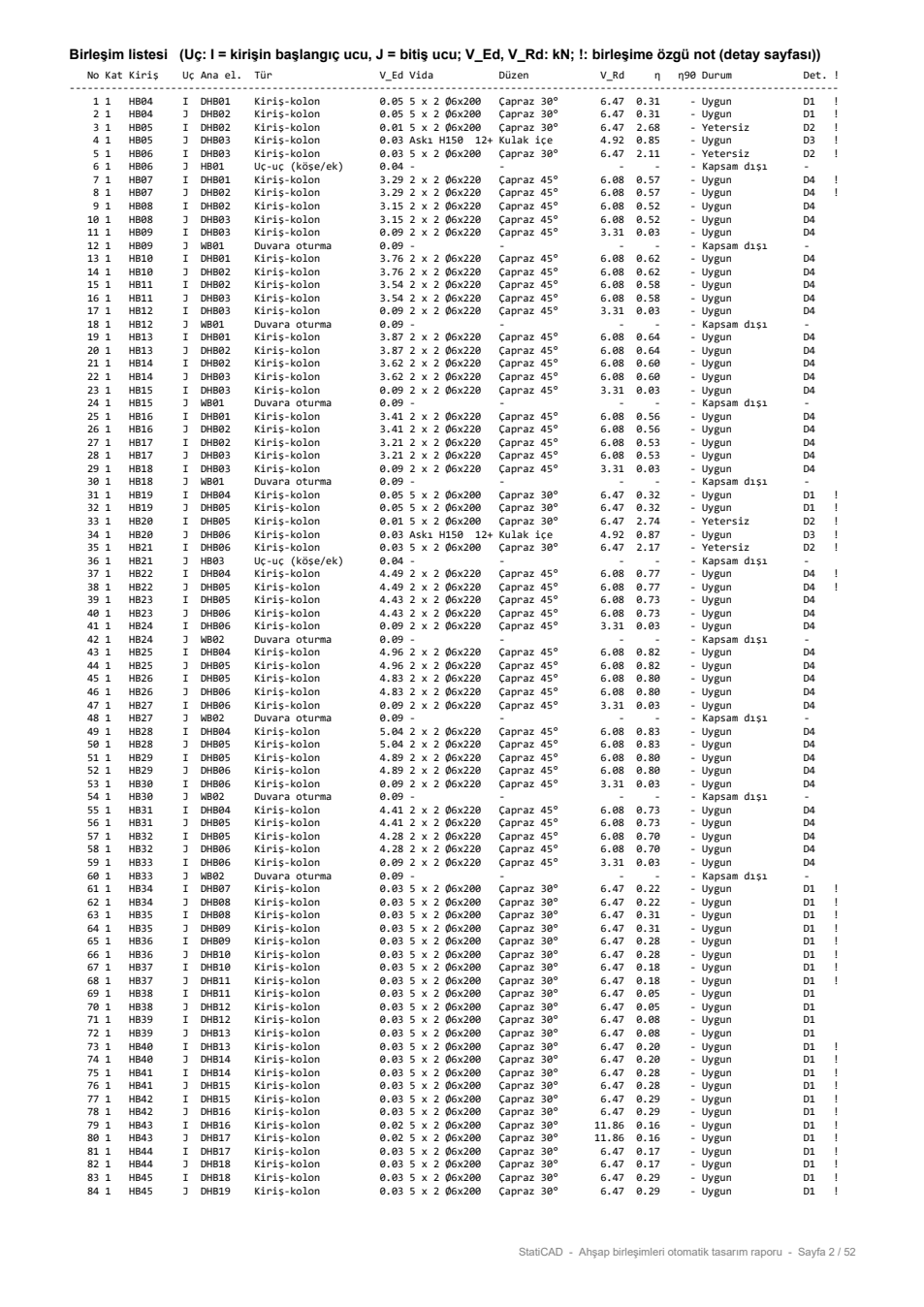
The "!" sign next to the status: An exclamation mark in the Status column, as in Suitable !, shows that there is a warning note specific to that connection: a beam also running into the main member from the opposite face (staggering of the screws), an axis offset in the model, or a column face narrower than the beam. The note can be read, when the row is selected, in the Note lines at the top of the breakdown; in the report it appears with "!" in the connection list and, in the detail pages, with a summary of the notes of all connections of the type. In this example 886 connections are marked.
7. Examining the results
7.1 Detail types
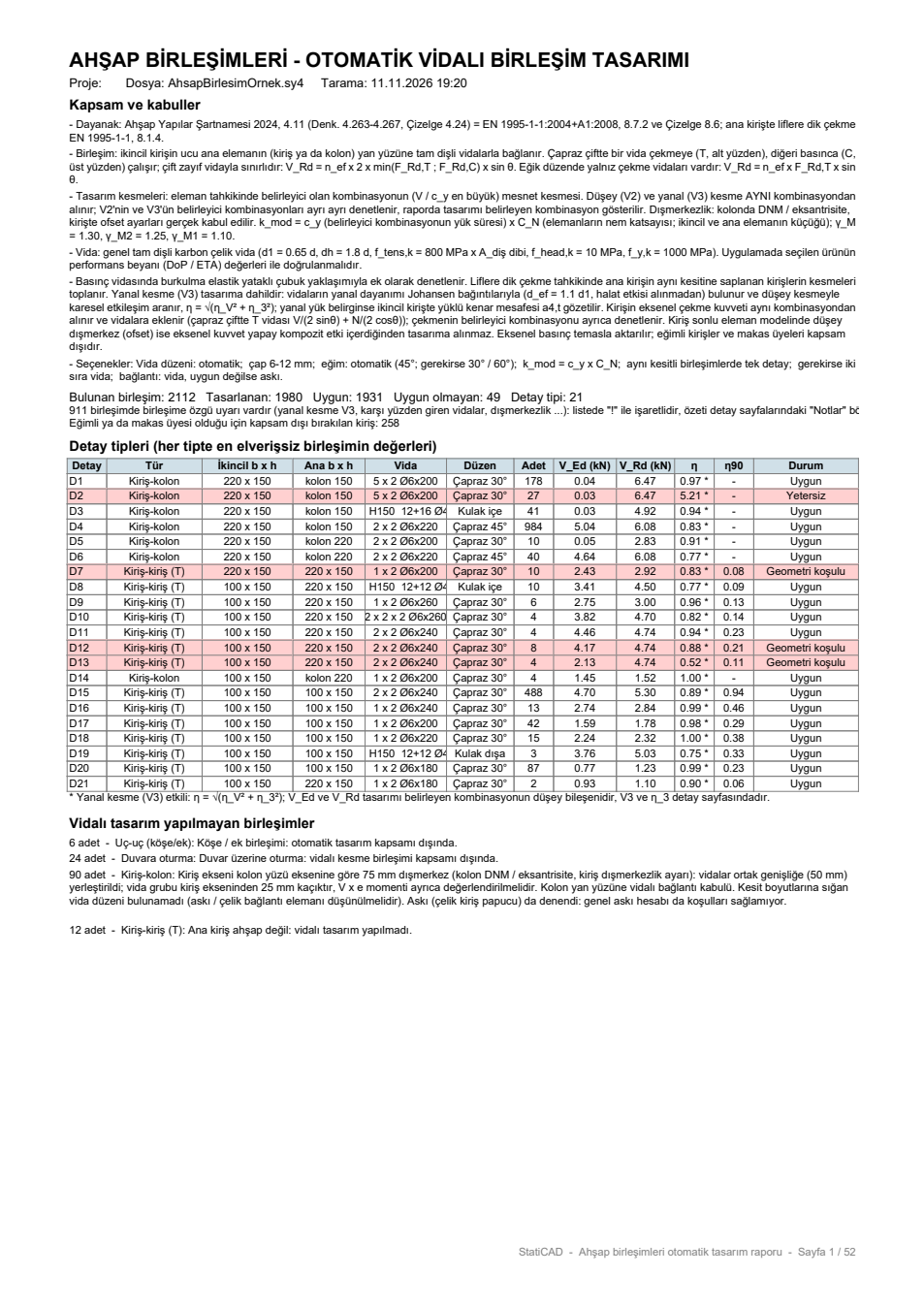
Connections with the same sections, the same screw arrangement and the same suitability status are collected in a single detail type. The types formed in this example:
Table 8 – Detail types (values of the most unfavourable connection in each type)
| Detail | Type | Secondary b × h | Main b × h | Screw | Arrangement | Number | VEd (kN) | VRd (kN) | η | η90 | Status |
|---|---|---|---|---|---|---|---|---|---|---|---|
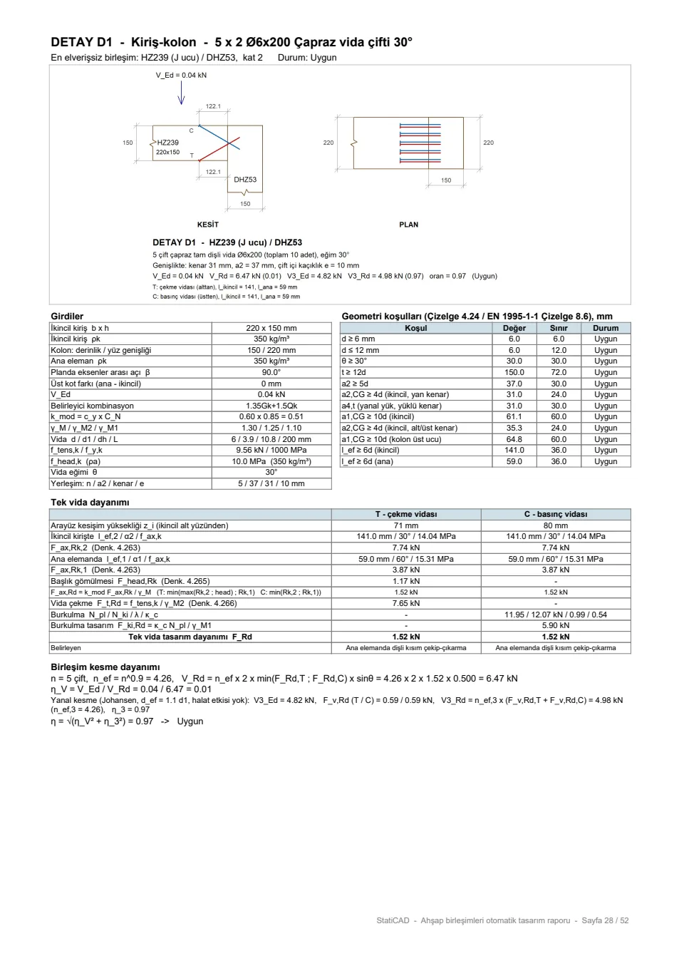
| D1 | Beam-to-column | 220 x 150 | column 150 | 5 x 2 Ø6x200 | Crossed 30° | 178 | 0.04 | 6.47 | 0.97 | – | Suitable |
| D2 | Beam-to-column | 220 x 150 | column 150 | 5 x 2 Ø6x200 | Crossed 30° | 27 | 0.03 | 6.47 | 5.21 | – | Inadequate |
| D3 | Beam-to-column | 220 x 150 | column 150 | 28 x 2 Ø4x60 | Crossed 0° | 41 | 0.03 | 4.92 | 0.94 | – | Suitable |
| D4 | Beam-to-column | 220 x 150 | column 150 | 2 x 2 Ø6x220 | Crossed 45° | 984 | 5.04 | 6.08 | 0.83 | – | Suitable |
| D5 | Beam-to-column | 220 x 150 | column 220 | 2 x 2 Ø6x200 | Crossed 30° | 10 | 0.05 | 2.83 | 0.91 | – | Suitable |
| D6 | Beam-to-column | 220 x 150 | column 220 | 2 x 2 Ø6x220 | Crossed 45° | 40 | 4.64 | 6.08 | 0.77 | – | Suitable |
| D7 | Beam-to-beam (T) | 220 x 150 | 220 x 150 | 1 x 2 Ø6x200 | Crossed 30° | 10 | 2.43 | 2.92 | 0.83 | 0.08 | Geometry condition |
| D8 | Beam-to-beam (T) | 100 x 150 | 220 x 150 | 24 x 2 Ø4x50 | Crossed 0° | 10 | 3.41 | 4.50 | 0.77 | 0.09 | Suitable |
| D9 | Beam-to-beam (T) | 100 x 150 | 220 x 150 | 1 x 2 Ø6x260 | Crossed 30° | 6 | 2.75 | 3.00 | 0.96 | 0.13 | Suitable |
| D10 | Beam-to-beam (T) | 100 x 150 | 220 x 150 | 2 x 2 Ø6x260 | Crossed 30° | 4 | 3.82 | 4.70 | 0.82 | 0.14 | Suitable |
| D11 | Beam-to-beam (T) | 100 x 150 | 220 x 150 | 2 x 2 Ø6x240 | Crossed 30° | 4 | 4.46 | 4.74 | 0.94 | 0.23 | Suitable |
| D12 | Beam-to-beam (T) | 100 x 150 | 220 x 150 | 2 x 2 Ø6x240 | Crossed 30° | 8 | 4.17 | 4.74 | 0.88 | 0.21 | Geometry condition |
| D13 | Beam-to-beam (T) | 100 x 150 | 220 x 150 | 2 x 2 Ø6x240 | Crossed 30° | 4 | 2.13 | 4.74 | 0.52 | 0.11 | Geometry condition |
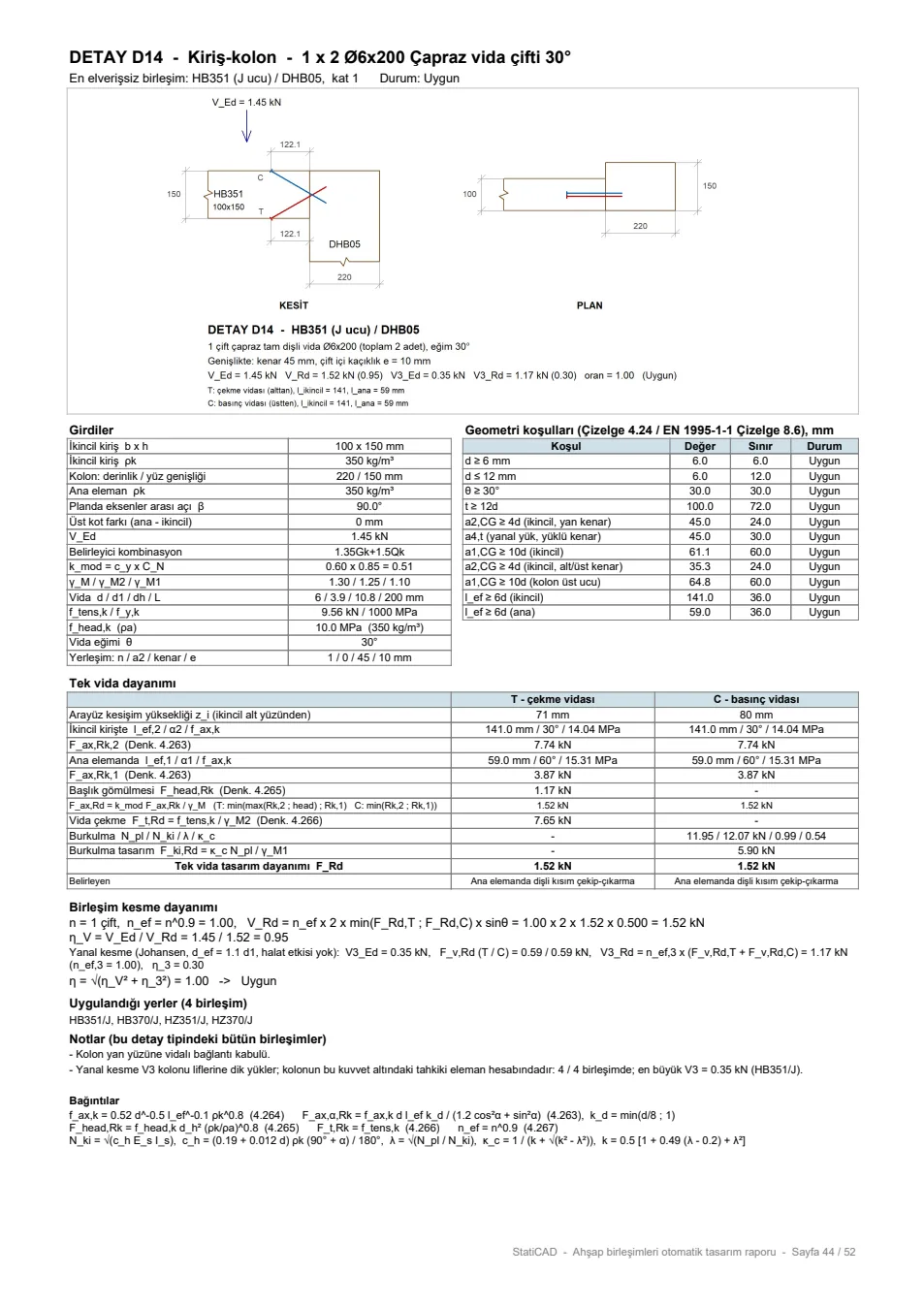
| D14 | Beam-to-column | 100 x 150 | column 220 | 1 x 2 Ø6x200 | Crossed 30° | 4 | 1.45 | 1.52 | 1.00 | – | Suitable |
| D15 | Beam-to-beam (T) | 100 x 150 | 100 x 150 | 2 x 2 Ø6x240 | Crossed 30° | 488 | 4.70 | 5.30 | 0.89 | 0.94 | Suitable |
| D16 | Beam-to-beam (T) | 100 x 150 | 100 x 150 | 1 x 2 Ø6x240 | Crossed 30° | 13 | 2.74 | 2.84 | 0.99 | 0.46 | Suitable |
| D17 | Beam-to-beam (T) | 100 x 150 | 100 x 150 | 1 x 2 Ø6x200 | Crossed 30° | 42 | 1.59 | 1.78 | 0.98 | 0.29 | Suitable |
| D18 | Beam-to-beam (T) | 100 x 150 | 100 x 150 | 1 x 2 Ø6x220 | Crossed 30° | 15 | 2.24 | 2.32 | 1.00 | 0.38 | Suitable |
| D19 | Beam-to-beam (T) | 100 x 150 | 100 x 150 | 24 x 2 Ø4x50 | Crossed 0° | 3 | 3.76 | 5.03 | 0.75 | 0.33 | Suitable |
| D20 | Beam-to-beam (T) | 100 x 150 | 100 x 150 | 1 x 2 Ø6x180 | Crossed 30° | 87 | 0.77 | 1.23 | 0.99 | 0.23 | Suitable |
| D21 | Beam-to-beam (T) | 100 x 150 | 220 x 150 | 1 x 2 Ø6x180 | Crossed 30° | 2 | 0.93 | 1.10 | 0.90 | 0.06 | Suitable |
7.2 Beam-to-beam (T) connection
Type D15 (in 488 places): HZ491 (I end) / HZ347. Secondary 100 × 150 mm, main 100 × 150 mm; VEd = 4.70 kN (combination 1.35Gk+1.5Qk), kmod = 0.60 × 0.95 = 0.57. The selected arrangement is 2 x 2 Ø6x240, Crossed 30°; VRd = 5.30 kN, η = 0.94. Status: Suitable.
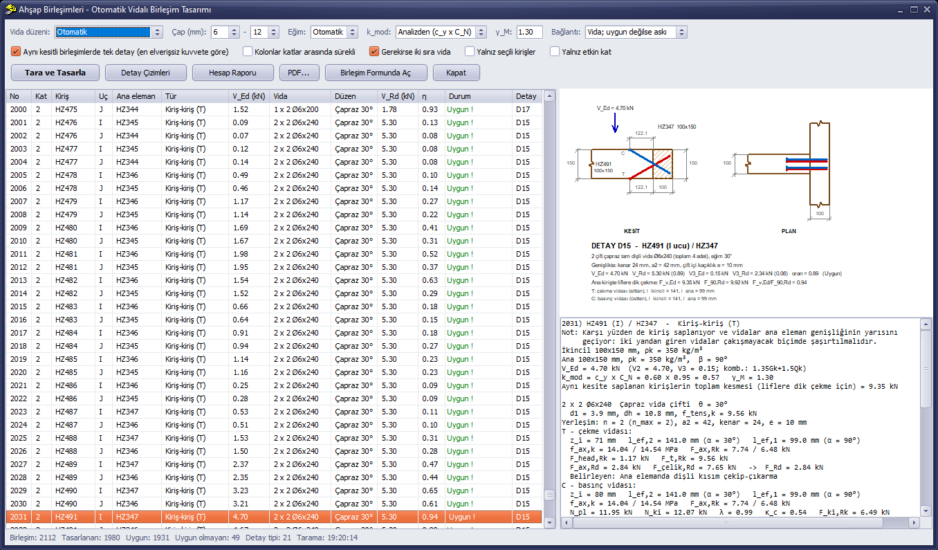
Figure 9 – When a beam-to-beam connection is selected in the list: detail preview and calculation breakdown
In the preview, the SECTION is the vertical section along the axis of the secondary beam: the secondary beam on the left, the cross-section of the main beam (hatched) on the right. The red line is the tension screw (T), the blue line the compression screw (C); the screw heads are shown with a short line. The horizontal dimensions are the distances of the screw entry points from the interface. The PLAN shows the position of the screws across the beam width.
The breakdown contains, in order: the inputs (governing combination, kmod), the selected screw and layout (n, a2, edge, eccentricity e within the pair), the interface crossing height zi for the T and C screws, the threaded lengths and grain angles in the two members, characteristic strengths, the single screw design strength and the governing failure mode, connection strength, tension perpendicular to the grain and geometry conditions ([+] satisfied, [X] not satisfied).
In this connection a beam also runs into the same section of the main beam from the opposite face; in the check of tension perpendicular to the grain, the shears of the two beams are added: Fv,Ed = 9.35 kN (the VEd of this beam is 4.70 kN). Since the screws exceed half the width of the main beam, the program also notes that the screws entering from both sides must be staggered.
7.3 Beam-to-column connection
Type D4 (in 984 places): HB28 (I end) / DHB04. Secondary 220 × 150 mm, main column (150 mm in the screw direction, face width 220 mm); VEd = 5.04 kN (combination Gk+Qk+0.4Sk+Ey1+0.3Ex2+0.3Edz), kmod = 1.10 × 0.85 = 0.94. The selected arrangement is 2 x 2 Ø6x220, Crossed 45°; VRd = 6.08 kN, η = 0.83. Status: Suitable.
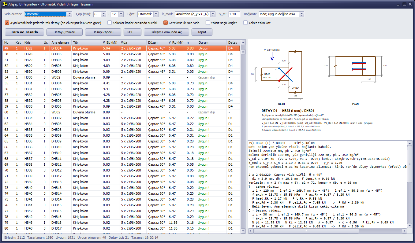
Figure 10 – A beam-to-column connection: the beam is connected to the side face of the post with screws
Since the grain in a column is vertical, the angle between the screw axis and the grain is 90° − θ. The end grain of the column is its top end; the distance of the centre of gravity of the threaded part in the column from the column top end is checked with the condition a1,CG ≥ 10d. If the column continues far above the beam, it is cut with a break line in the drawing.
Column side face assumption: The program assumes the beam end is connected to the side face of the column. If the column top end is at or below the bottom level of the beam, the beam-to-beam rule is checked first: if a beam passes uninterrupted (or a stronger beam) through the node, the end runs into that beam and is designed as a beam-to-beam connection; otherwise the beam is considered to sit on the column (status Bearing), and no screwed shear connection is designed (the bearing check is in the member calculation).
7.4 Column eccentricity: if the beam axis does not pass through the middle of the column face
In the finite element model the member nodes coincide; the real eccentricity is given in the column by the DNM / eccentricity settings and in the beam by the eccentricity and Offset settings (Bond Beam Properties › Offset: Offset2 vertical, Offset1 along the axis) and is taken as such in the connection design. In this model the posts are connected to the node by one edge (DNM); therefore in 50 connections the axis of the beam passes not through the middle but through the edge of the column face it is connected to. The screws are placed within the overlapping width of the beam and the column face; if the overlap is narrow, the number of screws that fit decreases, and if there is no overlap at all, the connection is not designed. When the screw group is off the beam axis, the resulting moment V · e must be evaluated separately (a note is made).
Example: HZ134 (I end) / DHZ07. Secondary 220 × 150 mm, main column (220 mm in the screw direction, face width 150 mm); VEd = 0.05 kN (combination 1.35Gk+1.5Qk), kmod = 0.60 × 0.85 = 0.51. The selected arrangement is 2 x 2 Ø6x200, Crossed 30°; VRd = 2.83 kN, η = 0.91. Status: Suitable. Column eccentricity 75 mm; the common width where the screws are placed is 110 mm.
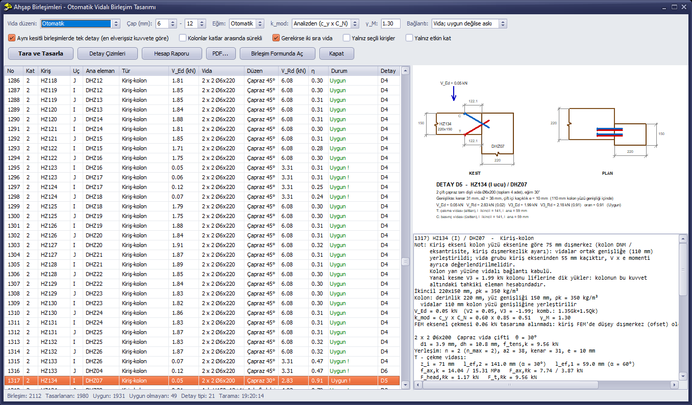
Figure 11 – A beam eccentric to the column face: the note in the breakdown; in the plan the column and the screw group in their real positions
7.5 Connections designed with a hanger (steel joist hanger)
When the Connection option is at its default (Screw; hanger if not suitable), a hanger is tried for connections where the screwed arrangement does not satisfy the conditions or does not fit into the section; if the hanger satisfies all conditions, the connection is designed with the hanger. In this model 54 connections were solved with a hanger. The calculation is generic (there is no product catalogue): U-shaped 2 mm sheet, ring-shank anchor nail Ø4; the secondary beam nails, the main member nails (shear + tension from the eccentricity moment), the shear of the sheet and tension perpendicular to the grain in the main beam are checked. The dimensions, nail pattern and performance declaration (DoP / ETA) of the selected product must meet the values found.
Example: HZ05 (J end) / DHZ03 — Hanger H150 12+16 Ø4x60: hanger height H = 150 mm, 12 nails in the secondary beam, 16 nails Ø4×60 in the main member (flanges turned inward); VRd = min(6.78; 4.92; 69.28) = 4.92 kN, VEd = 0.03 kN, η = 0.94.
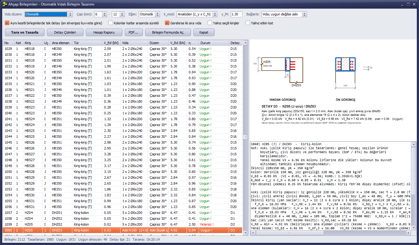
Figure 12 – A connection designed with a hanger: side and front view, hanger calculation in the breakdown
7.6 Unsuitable connections
In this example 49 connections are not suitable (Inadequate: 27, Geometry condition: 22). The most numerous group:
Type D2 (in 27 places): HZ241 (I end) / DHZ54. Secondary 220 × 150 mm, main column (150 mm in the screw direction, face width 220 mm); VEd = 0.03 kN (combination 1.35Gk+1.5Qk), kmod = 0.60 × 0.85 = 0.51. The selected arrangement is 5 x 2 Ø6x200, Crossed 30°; VRd = 6.47 kN, η = 5.21. Status: Inadequate.
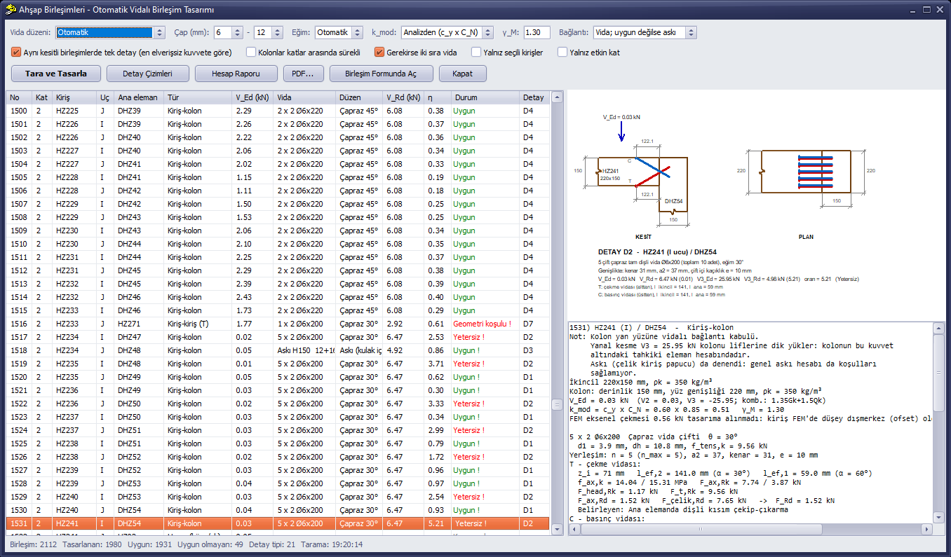
Figure 13 – An unsuitable connection: status in red in the list; ratio and conditions in the breakdown
If the status is Inadequate, even the strongest screw arrangement that complies with the geometry conditions does not carry the shear; if it is Geometry condition, no arrangement fits the section while satisfying the conditions. In both cases the options are:
- increase the width of the secondary beam (more screws fit side by side) or its height (longer screws, larger end distance);
- make the beam sit on top of the post (bring the column top level to the beam bottom level) – the shear is transferred by bearing;
- if the column continues uninterrupted in the upper storey, turn on the Columns continuous between storeys option (Section 8);
- use a hanger / steel fastener instead of a screwed connection (it can be calculated by hand in the connection form);
- if the product ETA allows smaller spacings, verify the calculation by hand with those values.
7.7 Beams running in close to the end of the main beam
In this model the blocking pieces are separate from post to post; each piece is connected to the side face of the post at its ends, that is, it is cut at the post face. If a floor joist runs into such a piece right next to a post, the screws fall in the end zone of the main piece. The condition a1,CG ≥ 10d in Table 4.24 is checked here to the physical end of the main beam (the post face); even with the smallest screw diameter, 60 mm is required. In this example 22 connections do not satisfy this condition and their status becomes Geometry condition.
Example: HB375 (J end) / HB235. Secondary 100 × 150 mm, main 220 × 150 mm; VEd = 4.17 kN (combination 1.35Gk+1.5Qk), kmod = 0.60 × 0.85 = 0.51. The selected arrangement is 2 x 2 Ø6x240, Crossed 30°; VRd = 4.74 kN, η = 0.88. Status: Geometry condition. The distance between the side face of the secondary beam and the end of the main piece at the post face is 12 mm (limit 10d = 60 mm).
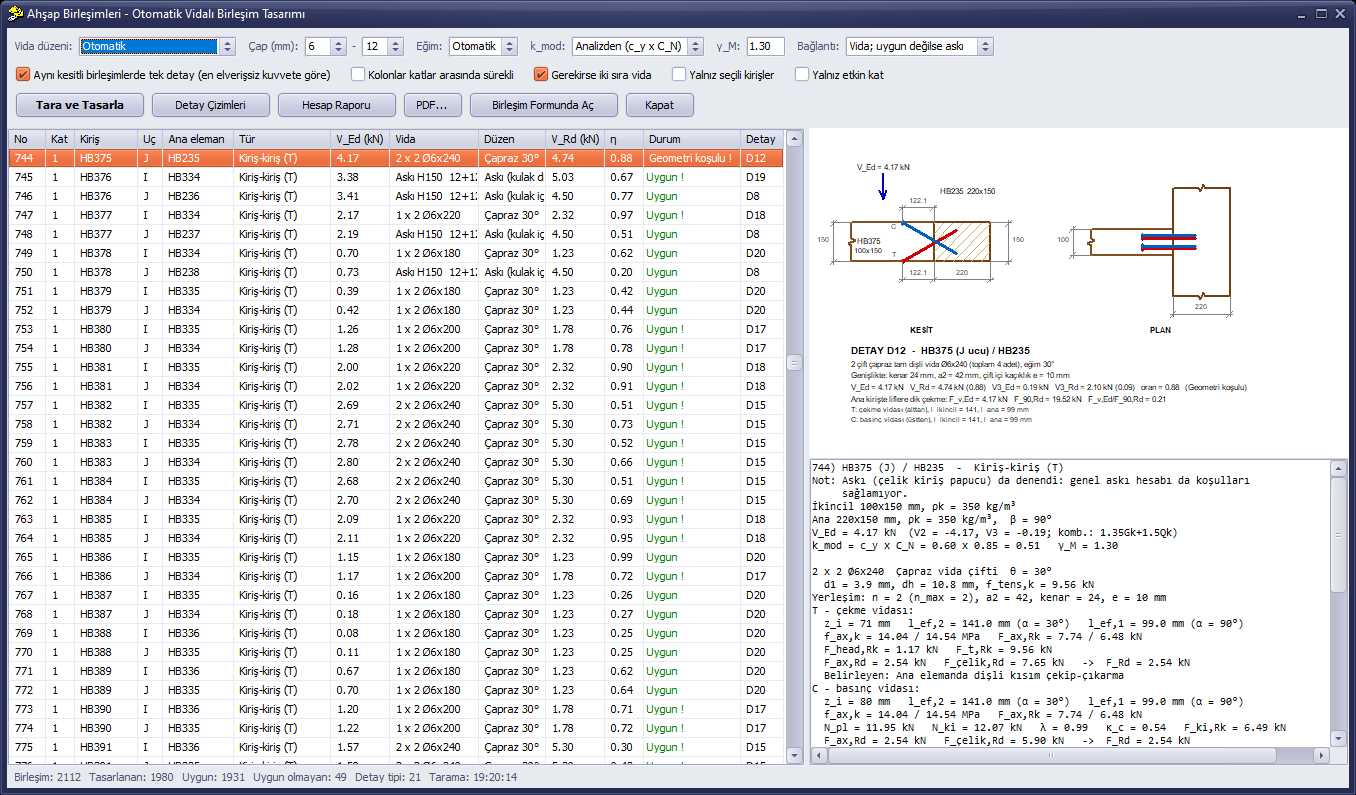
Figure 14 – A connection close to the end of the main beam: status "Geometry condition"; in the list of conditions at the end of the breakdown, the line a1,CG ≥ 10d (main beam end) is marked with [X]
Solution: move the floor joist away from the post (or connect it directly to the post), run the blocking continuously past the post, or use a hanger / steel fastener at that end. If the main beam is only split in the model at that point (it continues in the same direction and there is no column side face connection in between), or runs continuously by sitting on top of the column, this condition is not checked.
7.8 Rows that are not designed
Ends sitting on walls, corner / splice connections and connections that could not be designed appear in the list; the reason is written as a Note in the breakdown of the selected row. The reasons in this example:
Table 9 – Rows without screwed design
| Status | Number | Note |
|---|---|---|
| Could not be designed | 90 | The beam axis is 75 mm eccentric to the column face axis (column DNM / eccentricity, beam eccentricity setting): the screws were placed in the common width (50 mm); the screw group is 25 mm off the beam axis, and the moment V x e must be evaluated separately. Assumption of a screwed connection to the column side face. No screw arrangement fitting the section dimensions was found (a hanger / steel fastener should be considered). A hanger (steel joist hanger) was also tried: the generic hanger calculation does not satisfy the conditions either. |
| Out of scope | 24 | Bearing on a wall: outside the scope of the screwed shear connection. |
| Could not be designed | 12 | The main beam is not timber: no screwed design was made. |
| Out of scope | 6 | Corner / splice connection: outside the scope of automatic design. |
8. Effect of the options
The results obtained when options are changed on the same model and recalculated with Scan and Design:
Table 10 – Option trials
| Option | Designed | Suitable | Unsuitable | Detail types | Comment |
|---|---|---|---|---|---|
| Default (single detail on, columns not continuous) | 1980 | 1931 | 49 | 21 | The results in the article. |
| "Single detail for connections of the same section" off | 1980 | 1931 | 49 | 49 | Each connection is designed according to its own force: shorter screws in places, but many more detail types. |
| "Columns continuous between storeys" on | 1980 | 1937 | 43 | 26 | No end distance is checked for the top end of the posts on the lower storey; in connections at the column top end a steeper (45°) and stronger screw can be selected. |
| Screw arrangement: Inclined (tension only) | 1980 | 1920 | 60 | 18 | The number of screws is halved, but the strength of the connection also falls; it may not be enough in narrow sections. |
| Diameter range 8 – 12 mm | 1972 | 1900 | 72 | 19 | A thick screw needs larger edge / end distances and width; it does not fit narrow beams. |
| kmod = 0.80 (fixed) | 1980 | 1947 | 33 | 17 | The same kmod in all connections. |
9. Detail drawings
The Detail Drawings button transfers the most unfavourable connection of each detail type to the drawing screen with its section and plan view, dimensions, screw label and the list of places where it is applied; on the right it also draws the connection layout plan for each storey. The command opens the drawing screen itself and starts a new drawing (save any unsaved drawing on the screen first); 1 unit = 1 cm.
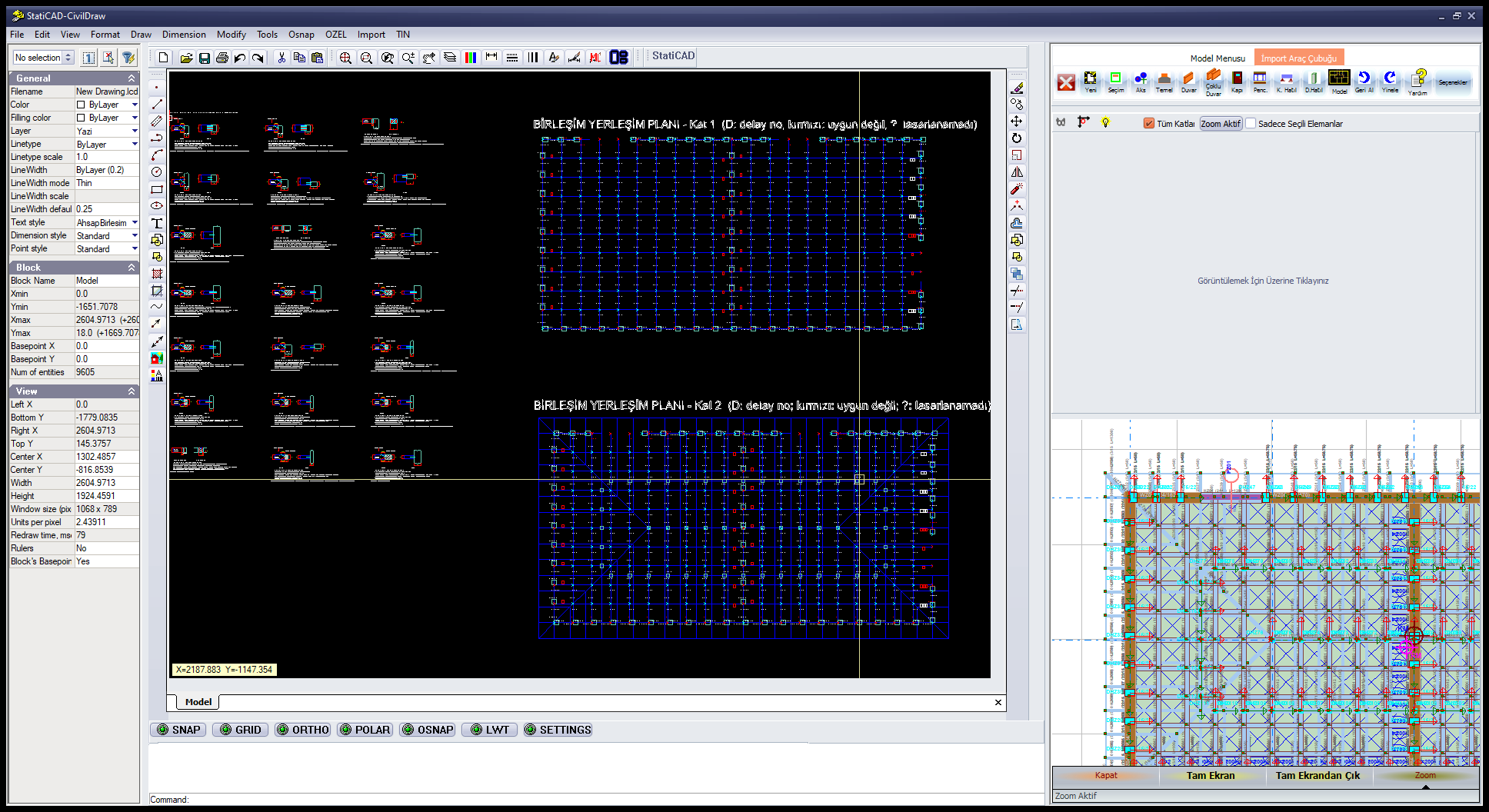
Figure 15 – Drawing screen: detail sheet on the left, connection layout plans storey by storey on the right
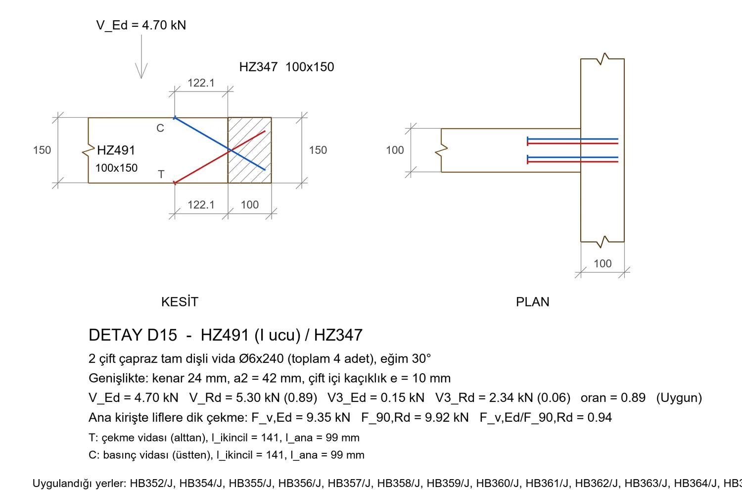
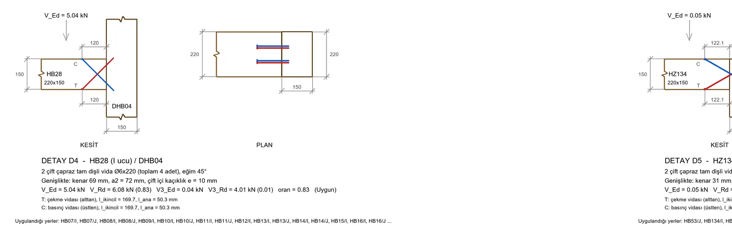
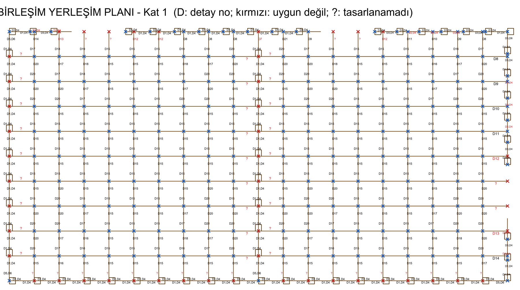
Figure 18 – Connection layout plan: beam axes, posts and the detail number at each beam end
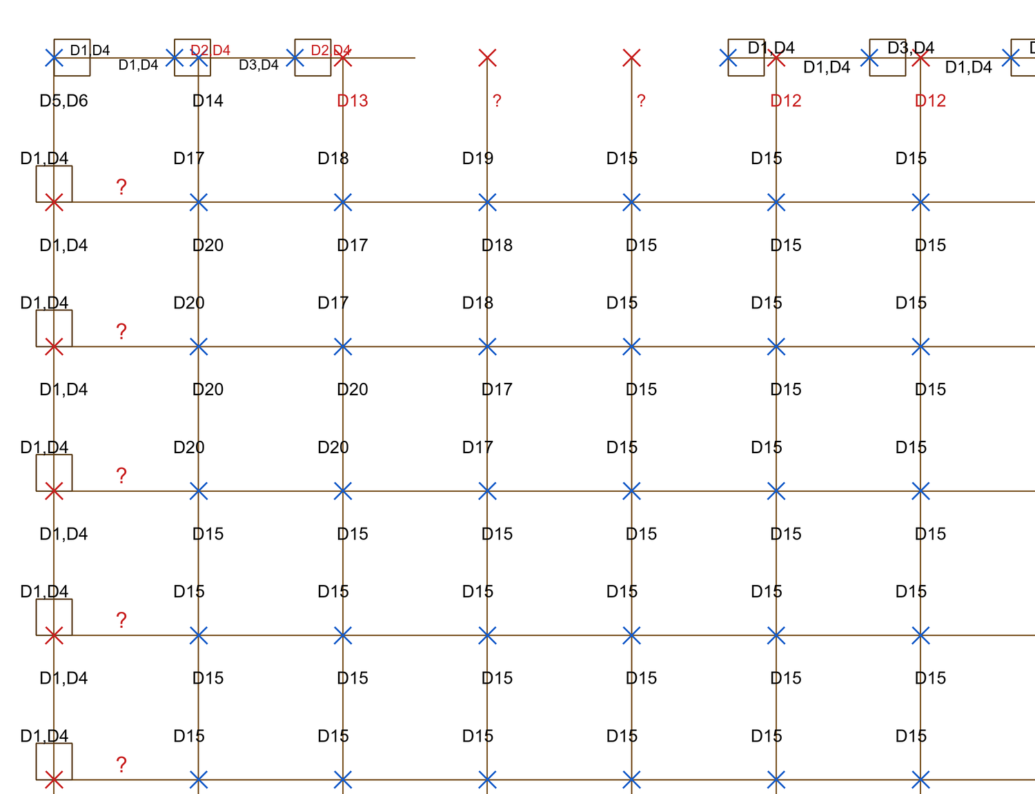
Figure 19 – Close-up of the layout plan: the detail numbers of ends that fall close together (blocking at different levels) are collected in a single label
Table 11 – Drawing layers
| Layer | Content |
|---|---|
| KirisHatil | Outline of the secondary beam; beam axes in the layout plan |
| Hatil | Outline of the main member (beam / column) |
| AhsapVidaT | Tension screws (T), red; unsuitable ends in the layout plan |
| AhsapVidaC | Compression screws (C); suitable ends in the layout plan |
| Olcu, Olcu Yazi | Dimension lines and values |
| Yazi | Member names, titles, notes |
| Donatı Çerçeve | Hatching of the main beam cross-section |
10. Calculation report
The Calculation Report button opens the report in preview; the PDF… button writes directly to a file. The report consists of the following parts:
- Scope and assumptions, the options used, numbers of connections found / designed;
- Detail types table (the table in Section 7.1);
- Connections without screwed design (numbers by reason);
- Connection list: all connections, their forces and detail numbers;
- for each detail type a calculation page: drawing, inputs and governing combination, geometry conditions, single screw strengths, connection strength, tension perpendicular to the grain, places where applied, the notes of all connections of that type (e.g. in how many connections the lateral shear V3 is significant and its largest value) and the relations used. If the list and notes do not fit on the page, a continuation page of the type is opened.
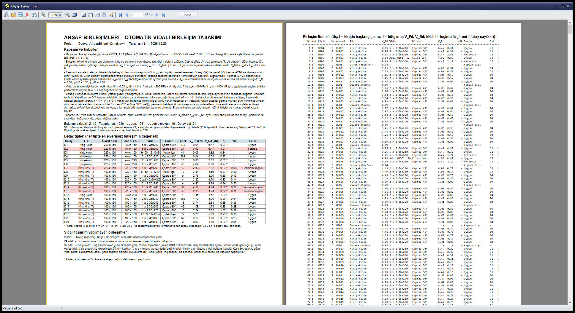
Figure 20 – Report preview
11. Verification by hand
In this section the most unfavourable connection of type D15 (HZ491, I end / HZ347) is recalculated independently of the program. Inputs: secondary beam 100 × 150 mm, main beam 100 × 150 mm, ρk = 350 kg/m³, VEd = 4.70 kN, kmod = 0.57, γM = 1.30; screw Ø6 × 240 (d1 = 3.9 mm, dh = 10.8 mm), 2 crossed pairs, θ = 30°.
- Lengths of the tension screw (T). The screw head is at the bottom face of the secondary beam; it crosses the interface at a height zi = 70.5 mm: lef,2 = zi / sin θ = 70.5 / 0.500 = 141.0 mm; lef,1 = L − lef,2 = 240 − 141.0 = 99.0 mm.
- Withdrawal in the secondary beam (α = 30°): fax,k = 0.52 · 6−0.5 · 141.0−0.1 · 3500.8 = 14.04 MPa; Fax,Rk,2 = 14.04 · 6 · 141.0 · 0.75 / (1.2 cos²30° + sin²30°) = 7.74 kN.
- Withdrawal in the main member (α = 90°): fax,k = 14.54 MPa; Fax,Rk,1 = 14.54 · 6 · 99.0 · 0.75 / 1.000 = 6.48 kN.
- Head embedment: Fhead,Rk = 10 · 10.8² · (350/350)0.8 = 1.17 kN. Head-side strength max(Fax,Rk,2; Fhead,Rk) = 7.74 kN.
- Single tension screw: Fax,Rd = kmod · min(7.74; 6.48) / γM = 0.57 · 6.48 / 1.30 = 2.84 kN; screw tension Ft,Rd = 9.56 / 1.25 = 7.65 kN → FRd,T = 2.84 kN.
- Compression screw (C). It enters from the top face and crosses the interface at zi = 79.5 mm: lef,2 = (h − zi) / sin θ = 141.0 mm, lef,1 = 99.0 mm; Fax,Rk,2 = 7.74 kN, Fax,Rk,1 = 6.48 kN → Fax,Rd = 2.84 kN.
- Buckling: Npl = π · 3.9² / 4 · 1000 = 11.95 kN; ch = 61.13 N/mm², Nki = √(ch · 210000 · Is) = 12.07 kN; λ = 0.99, κc = 0.54; Fki,Rd = 0.54 · 11.95 / 1.10 = 5.90 kN → FRd,C = 2.84 kN.
- Connection: nef = 20.9 = 1.87; VRd = nef · 2 · min(FRd,T; FRd,C) · sin θ = 1.87 · 2 · 2.84 · sin 30° = 5.30 kN; ηV = 4.70 / 5.30 = 0.89.
- Lateral shear: V3,Ed = 0.15 kN. def = 1.1 · 3.9 = 4.29 mm; fh,k = 18.54 MPa (secondary) / 18.54 MPa (main); My,Rk = 0.3 · 800 · def2.6 = 10583 N·mm; Johansen (t1 = lef,2, t2 = lef,1) → Fv,Rk = 1.49 and 1.49 kN; nef,3 = 1.79 (row parallel to the grain in the main beam: EN 1995-1-1 8.3.1.1(8); n0.9 in a column); V3,Rd = nef,3 · kmod · ΣFv,Rk / γM = 2.34 kN; η3 = 0.06.
- Combined: η = √(ηV² + η3²) = √(0.89² + 0.06²) = 0.89.
- Tension perpendicular to the grain: he = 95.2 mm (from the bottom edge of the main beam to the centre of gravity of the threaded part of the tension screw in the main beam); F90,Rk = 14 · 100 · √(95.2 / (1 − 95.2/150)) = 22.62 kN; F90,Rd = 0.57 · 22.62 / 1.30 = 9.92 kN; Fv,Ed = 9.35 kN (total of the beams running into the same section); η90 = 0.94.
Table 12 – Hand calculation – program comparison (kN)
| Quantity | By hand | Program |
|---|---|---|
| Fax,Rk,2 (T) | 7.74 | 7.74 |
| Fax,Rk,1 (T) | 6.48 | 6.48 |
| FRd,T | 2.84 | 2.84 |
| FRd,C | 2.84 | 2.84 |
| VRd | 5.30 | 5.30 |
| η | 0.89 | 0.89 |
| η90 | 0.94 | 0.94 |
Table 13 – Geometry conditions (d = 6 mm; mm)
| Condition | Value | Limit | Result |
|---|---|---|---|
| t ≥ 12d | 100.0 | 72.0 | ✓ |
| a2 ≥ 5d | 42.0 | 30.0 | ✓ |
| a1 ≥ 7d (in the main beam) | 42.0 | 42.0 | ✓ |
| a2,CG ≥ 4d (secondary, side) | 24.0 | 24.0 | ✓ |
| a1,CG ≥ 10d (secondary) | 61.1 | 60.0 | ✓ |
| a2,CG ≥ 4d (secondary, bottom/top) | 35.2 | 24.0 | ✓ |
| a2,CG ≥ 4d (main, bottom/top) | 54.8 | 24.0 | ✓ |
| a1,CG ≥ 10d (main beam end) | 2840.0 | 60.0 | ✓ |
| lef ≥ 6d (secondary) | 141.0 | 36.0 | ✓ |
| lef ≥ 6d (main) | 99.0 | 36.0 | ✓ |
12. Examination in the connection form
With a connection selected in the list, the Open in Connection Form button opens that connection in the Timber Connection Calculation form, where calculations are made by hand. The form switches to Screwed (axial) mode; for the designed connection, the axial check of the tension screw group is filled in with the design values and calculated: screw diameter and root diameter, ftens,k, the threaded length lef and grain angle in the governing member, number of screws, kmod, γM and the axial force on the group Fax,Ed = VEd / (2 sin θ) (VEd / sin θ in the inclined arrangement). The title of the form shows the connection that was opened (beam, its end and the main member).
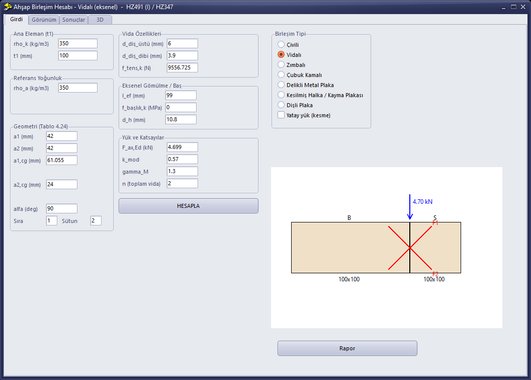
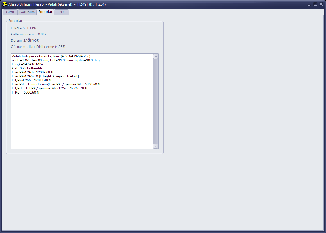
If the tension screw governs, the utilisation ratio in the form is the same as η in the automatic design; if the compression screw (buckling) governs, the form shows a smaller ratio, because the form checks only the tension screw. In the form, the strengths related to the timber are calculated with kmod / γM and the steel tensile strength of the screw with Ft,Rd = nef · ftens,k / γM2 (the same as in the automatic design). Different screws and spacings can be tried by changing the values; the Report button gives the report of this single check.
13. Small example: frame with four columns
To follow the automatic design in a small model built from scratch: a single-storey frame with 4.00 × 3.00 m spans and four C24 columns (14 × 14 cm); 14 × 28 cm main beams on the long sides, 12 × 24 cm beams on the short sides and three floor joists (10 × 24 cm) at 1.00 m spacing. An additional permanent load of 150 kg/m and an additional live load of 200 kg/m are given to the floor joists, and half of these to the edge beams (Add. G / Add. Q in the beam properties). The load factors are entered as 1.35 G + 1.5 Q: in a new project the G and Q factors come as 1.0 / 1.0; for limit state design they must be changed in Project General Settings.
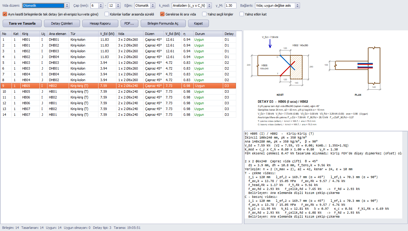
Figure 27 – Automatic design window in the small example
Table 14 – Small example: connections
| No | Beam / end | Main member | Type | VEd (kN) | Screw | Arrangement | VRd (kN) | η | Status |
|---|---|---|---|---|---|---|---|---|---|
| 1 | HB01 / I | DHB01 | Beam-to-column | 11.83 | 3 x 2 Ø6x260 | Crossed 45° | 12.61 | 0.94 | Suitable |
| 2 | HB01 / J | DHB02 | Beam-to-column | 11.83 | 3 x 2 Ø6x260 | Crossed 45° | 12.61 | 0.94 | Suitable |
| 3 | HB02 / I | DHB03 | Beam-to-column | 11.83 | 3 x 2 Ø6x260 | Crossed 45° | 12.61 | 0.94 | Suitable |
| 4 | HB02 / J | DHB04 | Beam-to-column | 11.83 | 3 x 2 Ø6x260 | Crossed 45° | 12.61 | 0.94 | Suitable |
| 5 | HB03 / I | DHB03 | Beam-to-column | 3.94 | 1 x 2 Ø6x260 | Crossed 45° | 4.72 | 0.83 | Suitable |
| 6 | HB03 / J | DHB01 | Beam-to-column | 3.94 | 1 x 2 Ø6x260 | Crossed 45° | 4.72 | 0.83 | Suitable |
| 7 | HB04 / I | DHB04 | Beam-to-column | 3.94 | 1 x 2 Ø6x260 | Crossed 45° | 4.72 | 0.83 | Suitable |
| 8 | HB04 / J | DHB02 | Beam-to-column | 3.94 | 1 x 2 Ø6x260 | Crossed 45° | 4.72 | 0.83 | Suitable |
| 9 | HB05 / I | HB02 | Beam-to-beam (T) | 7.59 | 2 x 2 Ø6x240 | Crossed 45° | 7.73 | 0.98 | Suitable |
| 10 | HB05 / J | HB01 | Beam-to-beam (T) | 7.59 | 2 x 2 Ø6x240 | Crossed 45° | 7.73 | 0.98 | Suitable |
| 11 | HB06 / I | HB02 | Beam-to-beam (T) | 7.59 | 2 x 2 Ø6x240 | Crossed 45° | 7.73 | 0.98 | Suitable |
| 12 | HB06 / J | HB01 | Beam-to-beam (T) | 7.59 | 2 x 2 Ø6x240 | Crossed 45° | 7.73 | 0.98 | Suitable |
| 13 | HB07 / I | HB02 | Beam-to-beam (T) | 7.59 | 2 x 2 Ø6x240 | Crossed 45° | 7.73 | 0.98 | Suitable |
| 14 | HB07 / J | HB01 | Beam-to-beam (T) | 7.59 | 2 x 2 Ø6x240 | Crossed 45° | 7.73 | 0.98 | Suitable |
Shear at the floor joist end by hand: beam load 1.35 · (150 + self-weight ≈ 10) + 1.5 · 200 ≈ 516 kg/m, span 3.00 m → VEd = q · L / 2 ≈ 7.59 kN; the program gives 7.59 kN. kmod = 0.80 × 1.00 = 0.80 (the program's own vertical load combination: cy = 0.80; CN = 1.00).
14. Tips and frequently encountered situations
- Status "No analysis", VEd = 0: the analysis has not been run or the model has been changed after the analysis; run the analysis, then Scan and Design.
- Load factors: VEd comes from the program's load combinations. The program's own vertical load combination is built with the G and Q factors in Project General Settings; in a new project these are 1.0 / 1.0, and 1.35 / 1.5 must be entered for limit state design.
- kmod seems small: cy comes from the governing combination; in user-defined combinations, if the duration of action of the loading is not selected as "Medium-Term Action" / "Instantaneous Action", 0.60 is taken. CN is the moisture selection of the member (Beam / Column Properties). If you wish, select a fixed kmod in the window.
- Many detail types: when the "Single detail for connections of the same section" option is on, the types reduce to section groups; when it is off, each force level selects its own screw length.
- The beam axis passes through the edge of the column: the DNM / eccentricity setting of the column is taken as real eccentricity; the screws are placed in the overlapping width of the beam and the column face. If the beam is in reality centred on the column face, centre the column on the node (DNM), and the connection is designed with the full width.
- Inclined beams and truss members are not scanned; their nodes transfer axial force. The number of skipped beams is written in the report.
- Lateral shear (V3) is included in the design: it is met by the lateral strength of the screws and combined with the vertical shear (η = √(ηV² + η3²)). If the lateral load is significant (η3 > 0.10), the screws are kept a4,t inside the loaded edge of the secondary beam; this may reduce the number of screws that fit in the width. In this example η3 > 0.10 in 476 connections; the largest V3 = 25.95 kN (beam HZ241, status: Inadequate). The axial tension force of the beam is taken into the design only when the beam has no vertical eccentricity (offset) in the FEM model (in a model with offset the axial force contains an artificial composite effect; it was not taken in this example).
- Screws entering from opposite faces: if beams run into the main beam from both sides and the screws exceed half the width of the main beam, the program makes a staggering note; in practice take care that the screws do not collide.
- The screws are a single row: if the number that fits in the beam width is not enough, the status is Inadequate; enlarge the section or select another connection type.
- The results are not saved to the file: keep the report and drawing after you obtain them; when the project is reopened, the analysis and scan are repeated.
The inputs in the article are for illustration; verifying the performance declaration (DoP / ETA) values of the screw product, the connection detail and the support conditions is the responsibility of the project's responsible engineer.