Worked Example: Timber Slab Vibration
1. About this article
This article uses screenshots to show how the timber slab vibration check of StatiCAD (ABTHYE 2024, Clauses 5.4.2, 4.8.4.7.1 and 4.8.2) is used from start to finish in a small two-storey timber building: project and storey settings, slab material and loads, conversion of the slab into timber joists (ribs), vibration definition on the calculation axis and Detect from model, composite (screwed OSB) and CLT slabs, analysis, reading the warnings, improving the design, report and drawings. All values are the actual inputs of the example building, all results are those the program gives for this example; the calculation of one slab has also been verified by hand (Section 13).
For all options and the theoretical background, see the article Timber Slab Vibration Check.
Edition: The timber slab vibration definition (the Timber Slab tab in the calculation axis properties) is available only in the StatiCAD Ultimate edition. The screenshots were taken with StatiCAD Ultimate V.10.0.1.0.
Example files: You can download the project files (ZIP) of the three stages in the article:
OrnekAhsapDoseme_ilk.sy4: initial design (DB01 joists 5×20 cm, Section 9);OrnekAhsapDoseme.sy4: improved design (DB01 joists 5×24 cm, Sections 10-12);OrnekAhsapDoseme_beton.sy4: composite with a cast concrete layer in DB02 (Section 14).
Open the file with File › Open and run the analysis; since the results are not saved in the project file, the analysis must be repeated each time it is opened.
2. Example building
A small two-storey timber house with a plan of 9.00 × 8.00 m. The load-bearing walls are 15 cm thick timber shear walls (stud panels with 10 mm OSB/3 sheathing on both faces). The slab above the ground floor (the slab of the 1st storey) consists of three pieces; the vibration check is carried out on these three slabs. The roof slabs are modelled as 12 cm CLT and no vibration definition has been made for them.
Table 1 – General information
| Item | Value |
|---|---|
| Plan | 9.00 × 8.00 m (x = 0…900 cm, y = 0…800 cm); interior load-bearing wall running full length at y = 400 cm, and at x = 450 cm (y = 0…400 cm) |
| Storeys | GROUND FLOOR and 1st STOREY, 3.00 m each |
| Building type / code | Timber building; TBDY 2018, DD-2, SS = 0.50, S1 = 0.14, ZC, I = 1, R = 3, D = 2 |
| Walls | Timber shear wall, 15 cm, material C24; 10 mm OSB/3 sheathing on both faces, connection stiffness kc = 800 N/mm; hold-down anchor kh = 5000 N/mm; shear anchor ka = 2000 N/mm, spacing 600 mm |
| DB01 (4.50 × 4.00 m) | Timber joist floor: C24 joists in the Y direction (span 4.00 m), 7 equally spaced joists (s = 56.2 cm); initial design 5×20 cm, improved design 5×24 cm; 18 mm OSB/2-OSB/3 sheathing |
| DB02 (4.50 × 4.00 m) | Same joists as the initial design of DB01 (5×20 cm); sheathing screwed to the joists (screws without pre-drilled holes d = 4 mm, s = 150 mm) – composite (4.8.2) |
| DB03 (9.00 × 4.00 m) | CLT slab 5 layers 40/20/40/20/40 mm (160 mm), C24 lamellas, outer layer grain in the Y direction (span 4.00 m), single span |
| Slab loads | Finish load G = 50 kg/m² (used as additional permanent mass in vibration), live load Q = 200 kg/m² |

Figure 1 – Ground floor plan (slab of the 1st storey): timber joists (blue) in DB01 and DB02, CLT in DB03, brown lines are timber shear walls

Figure 2 – Finite element model of the example building (frame elements): slab joists and equivalent frame elements of the walls
Plan orientation: In the StatiCAD plan view the y axis points downward: the façade at y = 0 appears at the top of the screen.
3. Summary of the check
Light, long-span timber slabs vibrate under human footsteps. This is not a load-bearing problem but a serviceability (comfort) problem. ABTHYE 5.4.2 requires two criteria: stiffness (instantaneous deflection w/F under a 1 kN point load at the middle of the slab) and comfort (unit impulse velocity response v against a heel impact). The calculation is in closed form, does not change the analysis results and is carried out on the slab calculation axis.
Table 2 – Check by slab type
| Slab type | Method | Criterion |
|---|---|---|
| Timber joist | 5.4.2 detailed (steps 1-6); optionally 4.8.4.7.1 simple | f1 > 8 Hz; a = w/F ≤ 4; b = −49.1·ln(a)+117; b ≥ 150 or v ≤ b(f1·ζ−1); otherwise b′ ≥ 50 and a = 10.786·e−0.0208·b′; performance: a ≤ 1 very good, ≤ 2 good, ≤ 3 slightly problematic, ≤ 4 may be problematic |
| Timber joist + composite | Same; (EI)L from the mechanically connected T-section (4.8.2 γ method, Kser Table 4.2a) | Same |
| CLT | 4.8.4.7.1 (mandatory) | w/F ≤ 1.5 mm/kN (1 m strip) and v ≤ 100(f1·ζ−1); f1 ≥ 8 Hz |
Basic quantities: f1 = π/(2L²)·√((EI)L/m) (5.10), n40 = {((40/f1)²−1)·(B/L)⁴·(EI)L/(EI)B}0.25 (5.12), v = 4·(0.4+0.6·n40)/(m·B·L+200) (5.11). m is the mass of permanent actions only (live load is not included).
4. Starting the program and project settings
When the program is opened, the start (dock) screen appears. New opens an empty project, and the Home icon opens the working screen.
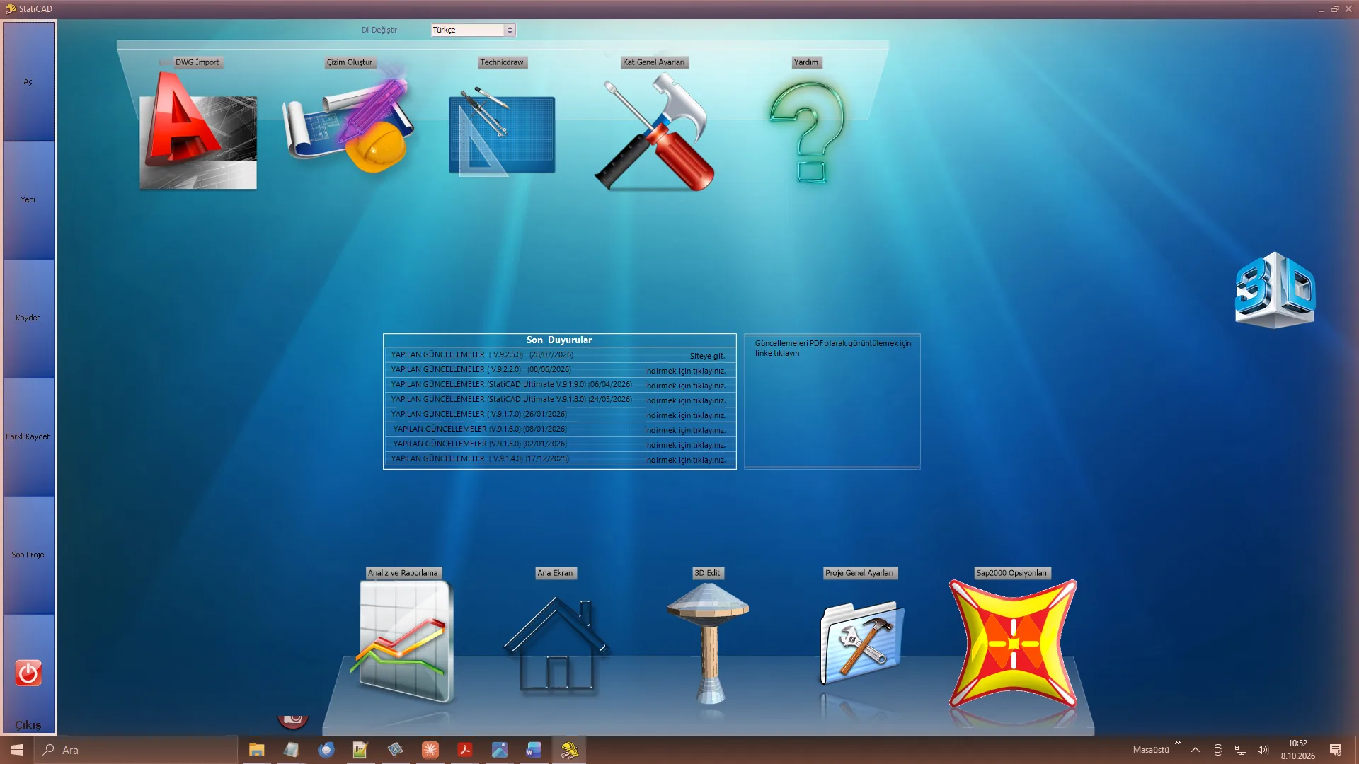
Figure 3 – Start (dock) screen
4.1 General Storey Settings
It is opened with KatAyar (Storey Settings) on the top toolbar. The example has two storeys (GROUND FLOOR and 1st STOREY, 300 cm). With Automatic Storey Name turned off, the storey names and output indices (Z, 1) have been given manually; the output index enters the element names (e.g. slab piece SZ3, beam HZ01).
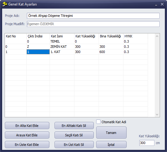
Figure 4 – General Storey Settings: storey names, heights and project name
4.2 Project General Settings: building type
In PrjAyar › Code Selection, Building Type: Timber Building, Earthquake Forces: TBDY 2018 and Ductility Level: Limited are selected. The vibration check is independent of the building type (timber slabs in a masonry or reinforced concrete building can also be checked); the building type determines the timber design of the walls and beams. In the example, the box “Deprem Yönetmeliği Düzensizlik Kontrolleri Yapılsın” (Perform earthquake code irregularity checks) in the Design tab has also been ticked (when it is off, an “Hata” (Error) row is added to the project checklist).

Figure 5 – Project General Settings › Code Selection: Timber Building, TBDY 2018
5. Building the model: walls and slabs
Walls are drawn with the Wall command and slabs with the Slab command (rectangular slab; the calculation axis is created together with the slab). For details of the drawing commands, see the article Modelling Tools. In the example there are 6 walls and 3 slabs on each storey.
5.1 Timber shear wall inputs
The walls are selected and edited together with right-click › Change Properties of Selected Walls. In General Settings the element type Timber Shear Wall is selected, and in Static/Material From Material Library › C24. In the Timber Shear Wall tab the panel sheathing (OSB/3, 10 mm, panel width 1220 mm), connection stiffness kc, stud sections, hold-down anchor (number nc, stiffness kh, strengths) and shear anchor (spacing ia, stiffness ka) are entered.
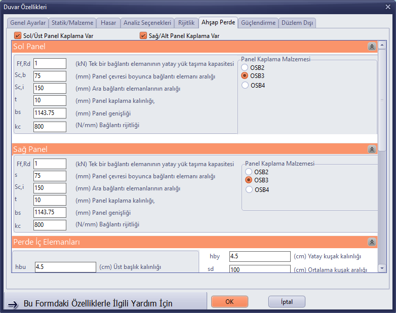
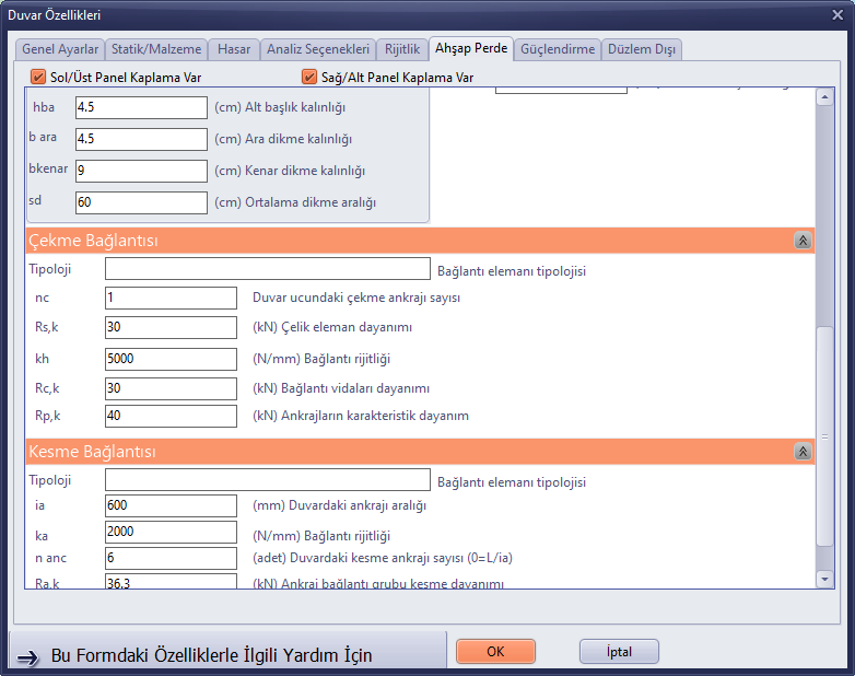
Enter the connection inputs according to the project: The finite element stiffness of a timber shear wall is the series sum of the stiffnesses of the panel, the fastener, the hold-down anchor and the shear anchor: K = 1/(1/Ks + 1/Kc + 1/Kh + 1/Ka). If kc, panel width, nc, kh, ia or ka remains zero, the wall stiffness comes out zero or undefined. In this case, at the start of the analysis the program completes the missing values with program defaults (t = 10 mm, bs = 1250 mm, Sc,b = 150 mm, kc = 996 N/mm, nc = 1, kh = 54826 N/mm, ia = 1000 mm, ka = 134725 N/mm), writes a warning for each wall with its name and the assigned values and with a “Seç” (Select) button, and adds the row “Ahşap perde girdileri varsayılanla tamamlandı” (Timber shear wall inputs were completed with defaults) to the project checklist. The defaults are not project-specific; enter the values according to the fastener and anchor documents. If no material is assigned to the wall, warnings such as “elastisite modülü sıfır alınamaz … 1 MPa olarak değiştirildi” (modulus of elasticity cannot be taken as zero … changed to 1 MPa) also appear. Since the slab vibration check does not use finite element results, it is not affected by these inputs, but the wall and earthquake calculations are.
5.2 Slab properties: OSB sheathing, thickness and loads
On the ground floor, three slabs are selected and, with right-click › Change Properties of Selected Slabs, the following values are entered:
- h = 1.8 cm (sheathing thickness; the joist sections come from the rib beams),
- Gfinish = 50 kg/m² (parquet, suspended ceiling etc. permanent load; used as additional permanent mass in vibration), Q = 200 kg/m²,
- From Material Library › OSB › OSB/2-OSB/3 t10 to 18 mm (Em,0 = 4930, Em,90 = 1980 MPa, ρ = 550 kg/m³).
For DB03 (CLT), h = 16 cm and the material C24 (Softwood) have also been entered; the self-weight of the slab is 420·0.16 = 67 kg/m².

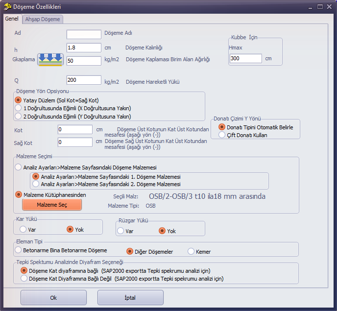
Slab and calculation axis windows: The command “Change Properties of Selected Slabs” first opens the properties window of the slab pieces, and then that of the calculation axes in the same selection. The second window also carries the title “Slab Properties”; it can be distinguished by the presence of the “Reinforcement Drawing X/Y Direction” boxes in the General tab. The vibration definition is made only in the calculation axis window.

Figure 10 – The Timber Slab tab in the slab (piece) window is in information mode: it states that the definition is to be made on the calculation axis and lists the enclosing calculation axes
6. Creating the timber joists (Convert to Ribs)
With DB01 selected, the command right-click › Create ribs/grid on selected slab divides the slab into strips along the joist axes and generates the joists. The original slab calculation axis does not change; the vibration check is carried out on this calculation axis.
- Rib/Grid Spacing = 60 cm, Division Direction = Y Direction (joists parallel to Y, span 4.00 m), Equal Spacing. With equal spacing, the 450 cm width is divided into 8 equal strips not exceeding 60 cm: 7 joists, spacing 56.25 cm.
- When Convert to Ribs is pressed, the joist properties window opens: Element Type = Timber, width 5 cm, height 20 cm, From Material Library › Timber › C24 (Softwood).
- In the Hinge tab, M3 (Major) is released at both ends (simply supported slab joist).
For DB02 the same steps have been repeated with the same values.
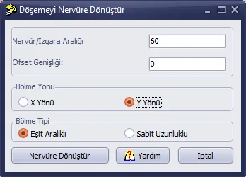


Division direction: “X Direction / Y Direction” is the direction of the joists. The joists should be placed along the short span (here 4.00 m, Y); the opposite increases the span and lowers f1.
7. Vibration definition on the calculation axis
The calculation axis is selected and the definition is made in the Timber Slab tab of the window opened with right-click › Change DB01 Slab Calculation Axis Properties. While the type is “None”, the other controls are disabled.
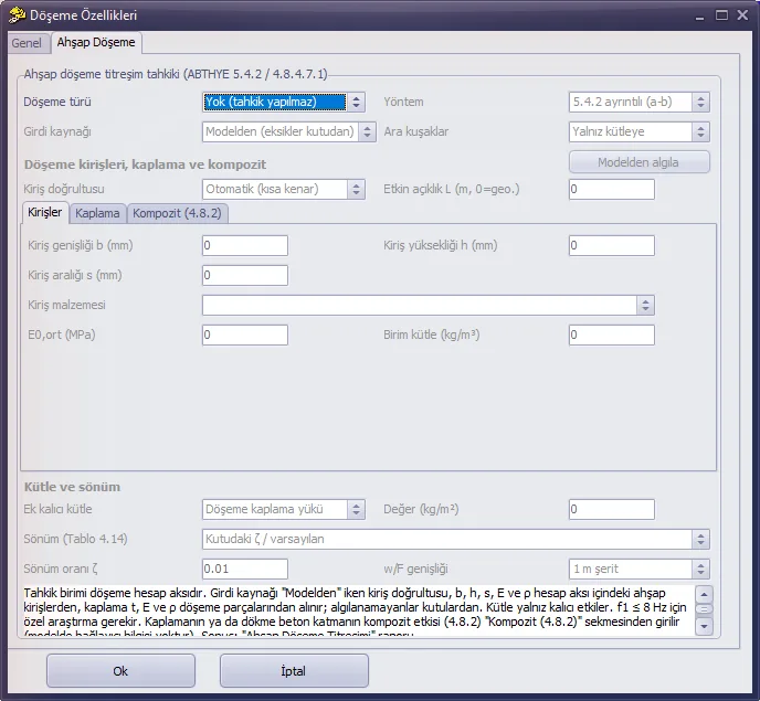
Figure 14 – Calculation axis window › Timber Slab: undefined state (type "None")
7.1 DB01: timber joist floor and Detect from model
- In the General tab of the calculation axis, the thickness 1.8 cm, G = 50 kg/m² and the OSB material are entered the same as for the slab pieces.
- In the Timber Slab tab: Slab type = Timber joist floor, Method = 5.4.2 detailed (a-b), Input source = Model (missing values from boxes).
- Detect from model is pressed. The program scans the timber joists and sheathing pieces inside the calculation axis, writes the values into the boxes and gives a summary at the bottom: main joists 7 pieces (Y), 50×200 mm, s = 562 mm, C24 E0 = 11000 MPa, ρ = 420; sheathing 8 pieces, t = 18 mm, OSB/2-OSB/3, E = 4930/1980 MPa, ρ = 550, finish load 50 kg/m².
- In the Sheathing inner tab the board layout remains Strong axis perpendicular to joists; for (EI)B, the E in the direction perpendicular to the joists, EB = Em,0 = 4930 MPa, is used.
- Mass and damping: additional permanent mass Slab finish load (50 kg/m²), damping ζ in box / default (0.01 for a timber joist floor).
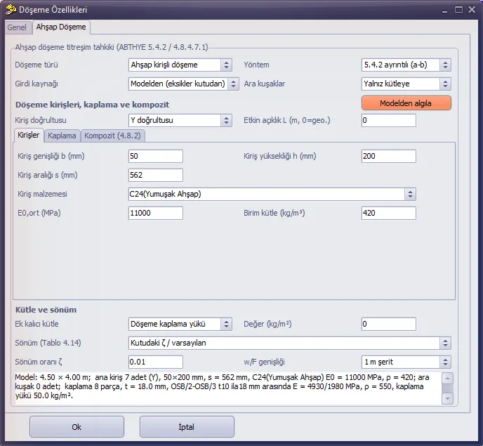
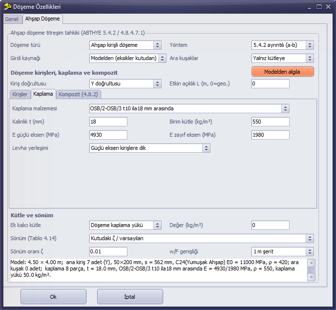
Input source: In “Model” mode, the calculation uses the values currently detected from the model, not the values in the boxes; the boxes are only a fallback for inputs that cannot be detected. If the model changes (e.g. the joist section is enlarged, Section 10), the vibration calculation is also updated automatically. In the “Values in boxes only” mode, the calculation is carried out entirely with the entered values.
7.2 DB02: composite slab (screwed OSB, 4.8.2)
In DB02 the definition is made the same as for DB01, and the following values are entered in the Composite (4.8.2) inner tab:
- Composite type = Sheathing mechanically connected (4.8.2 T-section),
- Fastener = Nail/screw without pre-drilled holes (ρm1.5·d0.8/30), d = 4 mm, s = 150 mm (uniform spacing; smax = 0), n = 1,
- Support = Single span (l = L), Effective flange = Table 4.16 interior joist, Eflange = 0 (from the material).
The program takes Kser from Table 4.2a (ρm = √(ρjoist·ρsheathing)), the effective flange width from Table 4.16 (at most the joist spacing), and the E of the flange in the joist direction from the compressive E of the OSB material record (Ec,90 = 3000 MPa, since the strong axis of the board is perpendicular to the joists).
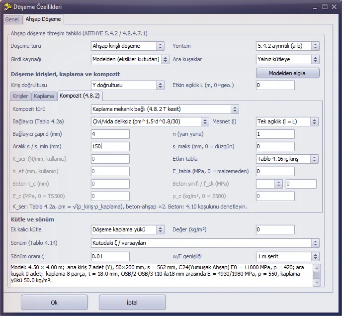
Figure 17 – Composite (4.8.2) page: screwed OSB flange
7.3 DB03: CLT slab (4.8.4.7.1)
- Slab type = CLT slab (4.8.4.7.1); the method is locked to 4.8.4.7.1 and the w/F width to the 1 m strip.
- Outer layer grain direction = Y direction (span 4.00 m; since the model does not carry the grain direction, it is selected in the box).
- Detect from model: the lamella material comes from the material of the calculation axis (C24, E0 = 11000 MPa, ρ = 420 kg/m³).
- Number of layers = 5, t1…t5 = 40/20/40/20/40 mm (from bottom to top; odd-numbered layers are longitudinal). The total of 160 mm is the same as the slab thickness in the model.
- Gr has been left empty: since the code gives no value for CLT, 50 MPa is used. Support condition = Single span (lref = L).
- The default damping for CLT is 0.025 (Table 4.14, CLT supported on two sides).
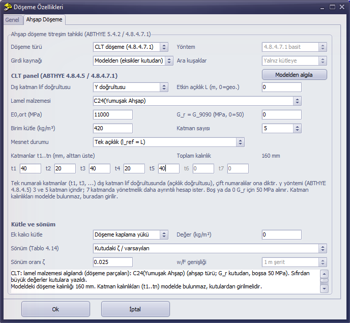
Figure 18 – CLT panel: 5 layers 40/20/40/20/40 mm, C24 lamellas, grain direction Y
8. Analysis
The Analysis button on the top toolbar opens the Static Analysis window; the analysis is run with Start Analysis. The vibration check is carried out automatically at the end of the analysis on all defined calculation axes; the results are written to the warnings list, the project checklist and the “Ahşap Döşeme Titreşimi” (Timber Slab Vibration) report page. No separate option is needed for the vibration check.
9. Initial results
The analysis warnings of the initial design (DB01 and DB02 joists 5×20 cm) are as shown. For DB01, the row “Bilgi – ahşap döşeme titreşim performansı (ABTHYE 5.4.2 adım 6) 2 < a ≤ 4 (az sorunlu / sorunlu olabilir; a < 2 tercih edilir): DB01 (a=2,04)” (Information – timber slab vibration performance (ABTHYE 5.4.2 step 6) 2 < a ≤ 4 (slightly problematic / may be problematic; a < 2 is preferred): DB01 (a=2.04)) appears. The other information row in the list states that the timber calculation axes (6 calculation axes on both storeys) have been excluded from the reinforced concrete slab calculation, the TS 500 thickness check and the reinforced concrete diaphragm check, and that the timber diaphragm (sheathing shear) must be evaluated separately.

Figure 19 – Analysis warnings of the initial design: DB01 a = 2.04 (slightly problematic)
Table 3 – Vibration results of the initial design
| Quantity | DB01 (5×20, bare) | DB02 (5×20, composite) | DB03 (CLT 5 layers) |
|---|---|---|---|
| L × B (m) | 4.00 × 4.50 | 4.00 × 4.50 | 4.00 × 9.00 |
| m (kg/m²) | 6.53 + 9.90 + 50.0 = 66.4 | 66.4 | 67.2 + 50.0 = 117.2 |
| (EI)L (kNm²/m) | 652.4 | 812.6 (bare 652.4; +25%) | 3033.7 |
| (EI)B (kNm²/m) | 2.396 | 2.396 | 410.7 |
| ζ | 0.010 | 0.010 | 0.025 |
| f1 (Hz) | 9.73 | 10.86 | 15.80 |
| n40 | 9.13 | 9.09 | 5.66 |
| w/F (mm/kN) | 2.044 | 1.641 | 0.440 (≤ 1.5) |
| v (m/Ns²) / limit | 0.01684 ≤ 0.01874 | 0.01678 ≤ 0.01764 | 0.00343 ≤ 0.06163 |
| a / result | 2.04 – slightly problematic (adequate) | 1.64 – good | satisfied (4.8.4.7.1) |
Slightly problematic = adequate: The program regards slabs with a ≤ 4 as adequate; the range 2 < a ≤ 4 is reported as information. If a exceeds 4, if b′ is smaller than 50, or if f1 ≤ 8 Hz, the slab is considered “YETERSİZ” (INADEQUATE) and is written to the project checklist. The code gives a ≤ 2 as the preferred performance; for this reason DB01 has been improved in the example.
10. Improving the design
Ways to reduce vibration: increasing the joist depth (EI grows with the cube of the section depth), reducing the spacing, reducing the span, connecting the sheathing mechanically to the joists (composite, DB02) or a cast concrete layer (Section 14). In DB01 the joist depth has been increased from 20 cm to 24 cm: the seven joists of DB01 are selected and, with right-click › Change Properties of Selected Beam/Bond Beams, the height is set to 24 cm.
Since the input source is “Model”, no other change is needed in the vibration definition; Detect from model shows the new section (50×240 mm). The analysis is run again.
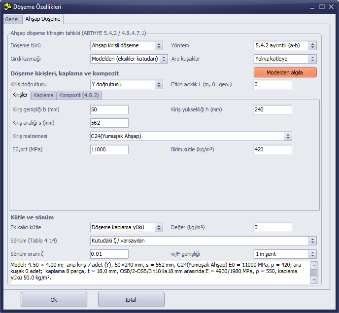
Figure 20 – Improved DB01: Detect from model finds the 50×240 mm joists
Table 4 – DB01: initial and improved design
| Quantity | Initial (5×20) | Improved (5×24) |
|---|---|---|
| EIjoist (kNm²) | 366.7 | 633.6 |
| (EI)L (kNm²/m) | 652.4 | 1127.4 |
| m (kg/m²) | 66.4 | 67.7 |
| f1 (Hz) | 9.73 | 12.67 |
| w/F (mm/kN) | 2.044 | 1.183 |
| b; v limit | 81.9; 0.01874 | 108.8; 0.01665 |
| v (m/Ns²) | 0.01684 | 0.01646 |
| a / performance | 2.04 – slightly problematic | 1.18 – good |

Figure 21 – Analysis warnings of the improved design: the vibration information row has disappeared
11. Project checklist and warnings
The row “Ahşap döşeme titreşimi (ABTHYE 5.4.2 / 4.8.4.7.1)” (Timber slab vibration (ABTHYE 5.4.2 / 4.8.4.7.1)) is written to the project checklist (the “Proje Hata Kontrolleri” (Project Error Checks) section in the report): if there is no problematic slab, the status is Yok (None) with the explanation “3 ahşap / CLT döşemenin tümünde titreşim koşulları sağlanıyor” (vibration conditions are satisfied in all 3 timber / CLT slabs); if there is an inadequate, out-of-scope (f1 ≤ 8 Hz) or incomplete-input slab, the status is Var (Present) with the slab list. If there is a composite slab with a concrete layer, the row “Ahşap döşemede beton katman (ABTHYE 4.10)” (Concrete layer in timber slab (ABTHYE 4.10)) is additionally added (Section 14).
Table 5 – Analysis warnings related to timber slab vibration
| Warning | When | What to do |
|---|---|---|
| … titreşim tahkiki YETERSİZ … (… vibration check INADEQUATE …) | a > 4, b′ < 50 (or, for CLT, w/F > 1.5 or the v limit exceeded) | Joist depth/spacing, composite, span |
| … f1 ≤ 8 Hz … özel araştırma gerekir (… a special investigation is required) | f1 ≤ 8 Hz (out of scope) | Increase the stiffness or reduce the mass |
| … titreşim tahkiki yapılamadı – Eksik/geçersiz girdi (… vibration check could not be performed – Missing/invalid input) | Box or model input missing (e.g. fastener diameter d) | Complete it in the Timber Slab tab |
| Bilgi – … 2 < a ≤ 4 (Information – … 2 < a ≤ 4) | Slightly problematic / may be problematic | a ≤ 2 is preferred |
| Bilgi – … kütlesi … %20'den fazla farklı (Information – … mass … differs by more than 20%) | Vibration mass differs greatly from the slab G in the program | Check the additional permanent mass and the slab loads |
| Bilgi – ahşap ızgara algılanan ama titreşim tanımı olmayan hesap aksları (Information – calculation axes with a detected timber grid but no vibration definition) | The calculation axis has ≥ 2 timber joists, type is “None” | Select a type |
| Uyarı – beton katmanlı kompozit … ABTHYE 4.10 (Warning – composite with concrete layer … ABTHYE 4.10) | Composite type “Cast concrete layer” | Verify that the supports are non-timber vertical load-bearing elements |
12. Report
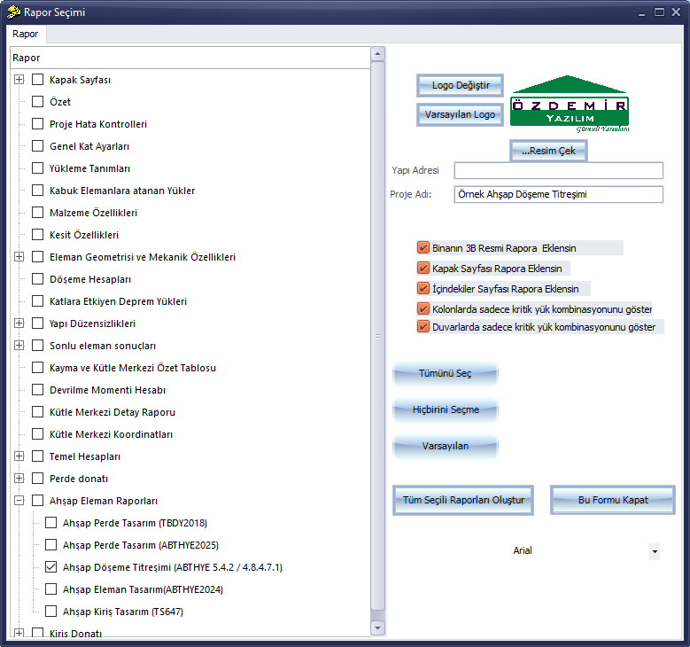
The Report button on the top toolbar (or Create Report in the Static Analysis window) opens the Report Selection. The vibration report is at the node Ahşap Eleman Raporları › Ahşap Döşeme Titreşimi (ABTHYE 5.4.2 / 4.8.4.7.1) (Timber Element Reports › Timber Slab Vibration). It is possible to tick only this node and press Create All Selected Reports.

The report first gives what the check is and its steps, then for each slab (1) inputs and input source, (2) mass, (3) stiffnesses (for composite Kser, γ1, a1, a2, (EI)ef; for CLT γi, ai, Ix,ef, Iy,net), (4) f1, (5) n40 and v, (6) w/F and the lines of steps 2-6 in the form relation = substituted value = result; at the end there are a summary and the symbols.
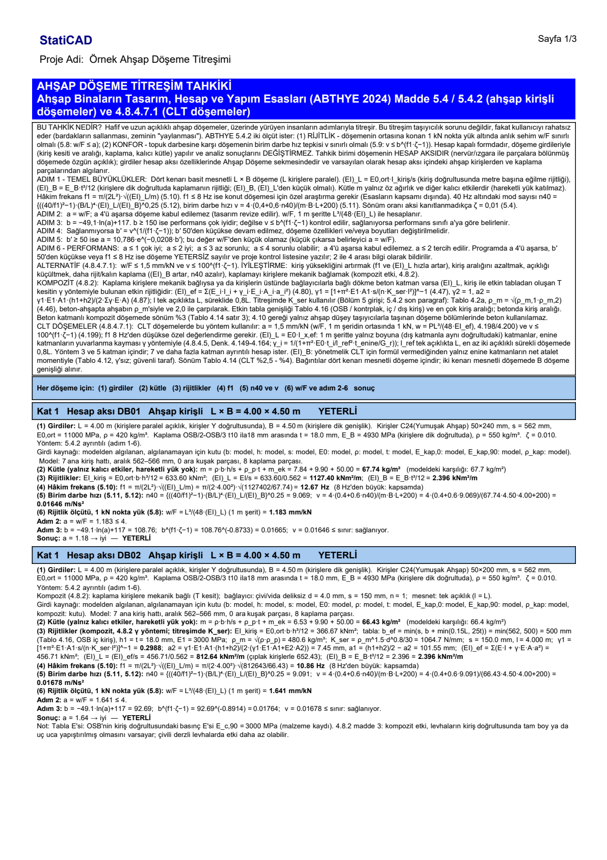
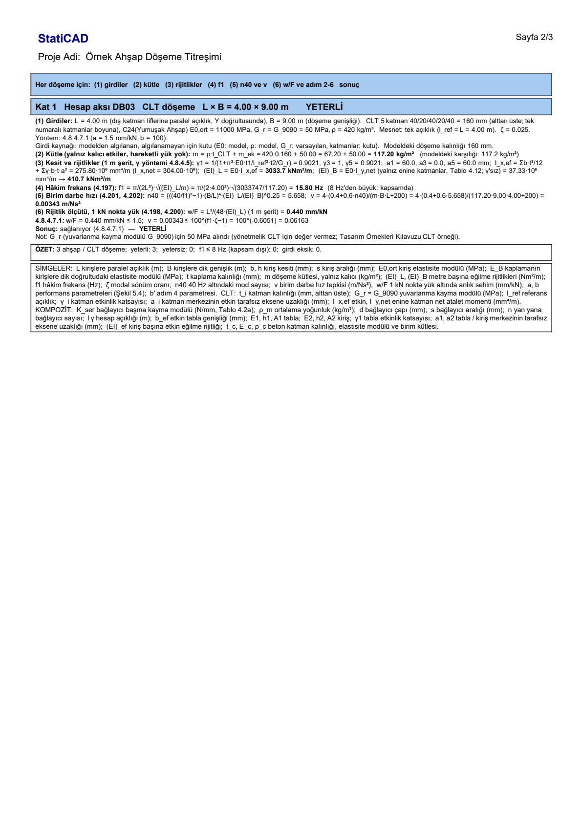
Note line: The program's assumptions are written in the “Not” (Note) line at the end of each slab: e.g. for DB02, the source of the flange E (OSB Ec,90 = 3000 MPa) and 4.8.2 item 3 (the assumption that the boards are full-length or glued end to end in the joist direction), and for DB03 the 50 MPa taken for Gr. These notes are written only to the report, not to the analysis warnings.
13. Hand verification
DB01 (improved): L = 4.00 m, B = 4.50 m, joist 50×240 mm C24, s = 0.562 m, OSB 18 mm.
- EIjoist = 11000·50·240³/12 = 6.336·10¹¹ Nmm² = 633.6 kNm²; (EI)L = 633.6/0.562 = 1127.4 kNm²/m.
- (EI)B = 4930·1000·18³/12·10⁻⁶ = 2396 Nm²/m.
- m = 7 joists·0.05·0.24·4.00·420 / (4.50·4.00) + 550·0.018 + 50 = 7.84 + 9.90 + 50 = 67.74 kg/m².
- f1 = π/(2·4.00²)·√(1127402/67.74) = 0.09817·129.0 = 12.67 Hz > 8 Hz.
- w/F = 4.00³/(48·1127402)·10⁶ = 1.183 mm/kN ≤ 4 (step 2).
- b = −49.1·ln(1.183)+117 = 108.8 < 150 → v limit = 108.8(12.67·0.01−1) = 108.8−0.8733 = 0.01665.
- n40 = {((40/12.67)²−1)·(4.50/4.00)⁴·1127402/2396}0.25 = (8.975·1.602·470.5)0.25 = 9.07; v = 4·(0.4+0.6·9.07)/(67.74·4.50·4.00+200) = 23.37/1419.3 = 0.01646 ≤ 0.01665 → satisfied (step 3).
- a = w/F = 1.18 → 1 < a ≤ 2: good.
DB02 (composite):
- ρm = √(420·550) = 480.6 kg/m³; Kser = 480.61.5·40.8/30 = 10536.7·3.031/30 = 1064.7 N/mm (Table 4.2a, screw without pre-drilled holes).
- beff = min(s; b + min(0.15L; 25t)) = min(562; 50 + min(600; 450)) = 500 mm (Table 4.16, OSB interior joist); A1 = 500·18 = 9000 mm².
- γ1 = [1 + π²·3000·9000·150/(1·1064.7·4000²)]−1 = [1 + 2.346]−1 = 0.2988 (4.47).
- a2 = 0.2988·3000·9000·(18+200)/(2·(0.2988·3000·9000 + 11000·50·200)) = 7.45 mm; a1 = 109 − 7.45 = 101.55 mm (4.87).
- (EI)ef = 3000·500·18³/12 + 0.2988·3000·9000·101.55² + 11000·50·200³/12 + 11000·10000·7.45² = 4.567·10¹¹ Nmm²; (EI)L = 456.7/0.562 = 812.6 kNm²/m (4.80).
The program results (Table 3, Table 4 and the report) are exactly the same as these values.
14. Composite with a cast concrete layer (variant)
Pouring a concrete layer connected to the joists with screws on top of the sheathing increases both the stiffness and the mass. In this variant, in the Composite (4.8.2) page of DB02, Composite type = Cast concrete layer (timber-concrete), Fastener = Nail/screw with pre-drilled holes, bolt, d = 8 mm, s = 150 mm, Concrete tc = 50 mm, Concrete class C25 have been selected (Ec and ρc = 0: TS 500 relation and 2500 kg/m³). The damping box switches to the default of the type: ζ = 0.03 (Table 4.14 row 3).

Figure 26 – Composite (4.8.2) page: cast concrete layer, C25, tc = 50 mm
Table 6 – DB02: screwed OSB and composite with a concrete layer
| Quantity | Screwed OSB | Concrete layer (50 mm C25) |
|---|---|---|
| Kser (N/mm) | 1064.7 | 2·4201.5·8/23 = 5987.8 (timber-concrete ×2) |
| Flange beff / E1 | 500 mm / 3000 MPa | s = 562 mm / Ec = 3250√25 + 14000 = 30250 MPa |
| γ1 | 0.299 | 0.071 |
| (EI)L (kNm²/m) | 812.6 | 2048.5 |
| (EI)B (kNm²/m) | 2.40 | 2.40 + 315.1 = 317.5 |
| m (kg/m²) | 66.4 | 66.4 + 125.0 = 191.4 |
| ζ | 0.010 | 0.030 |
| f1 (Hz) / w/F (mm/kN) | 10.86 / 1.641 | 10.16 / 0.651 |
| v / limit | 0.01678 / 0.01764 | 0.00274 / 0.0325 |
| a / performance | 1.64 – good | 0.65 – very good |
Since the concrete layer triples the mass, f1 decreases slightly, but because (EI)B and damping increase, v and w/F decrease markedly.
ABTHYE 4.10: concrete cannot be used in parts with timber vertical load-bearing elements: The code does not permit the use of concrete, reinforced concrete or similar heavy materials in the parts of floors that are carried only by timber vertical load-bearing elements. The program does not check the supports from the model; for every composite slab with a concrete layer it writes an analysis warning and the row "Ahşap döşemede beton katman (ABTHYE 4.10)" (Concrete layer in timber slab (ABTHYE 4.10)) (status Var, Present) to the project checklist. In this example, since the slab rests on timber shear walls, the concrete layer cannot be used; the variant is only to show the behaviour of the program. For timber slabs resting on masonry or reinforced concrete walls (e.g. strengthening of historic masonry buildings), timber-concrete composite can be applied.
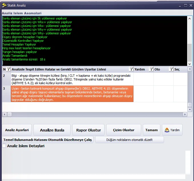
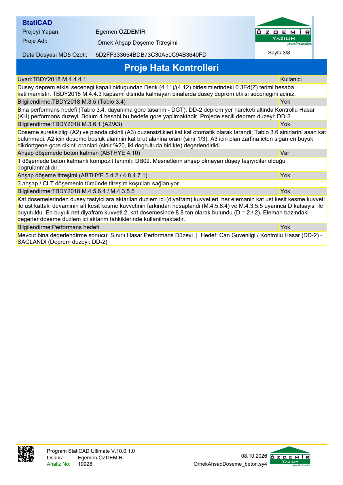
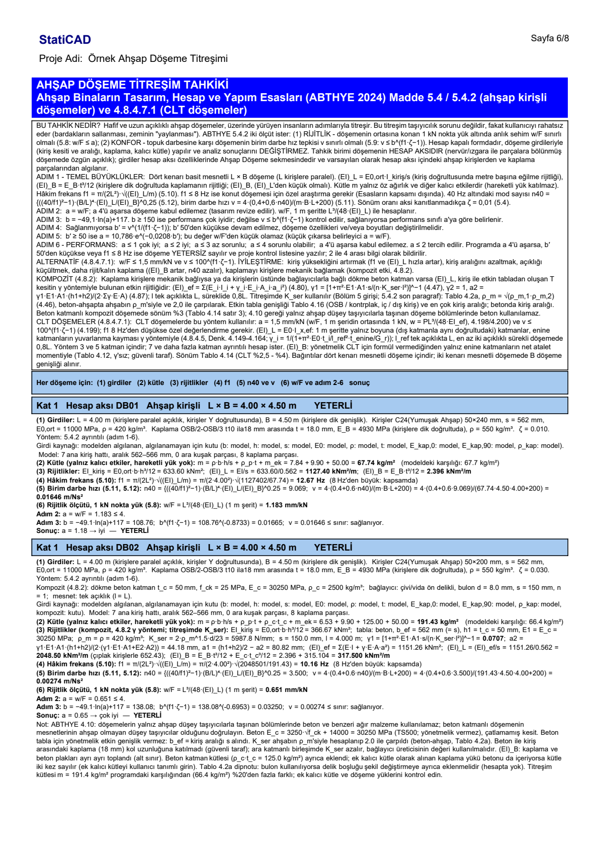
Figure 29 – Report: DB02 with concrete layer (Kser ×2, concrete slab in (EI)B, ζ = 0.03, notes)
Avoiding double counting of the mass: The mass of the concrete layer (ρc·tc) is added separately to the vibration mass. If the finish load of the slab also includes the concrete, the mass is counted twice; in this case enter the additional permanent mass as “User value”. If the concrete layer has been drawn in the model as a slab piece (input source “Model”), the program reports an input error: the source must be set to “Boxes only” and the sheathing must be entered according to the formwork board (or t = 0).
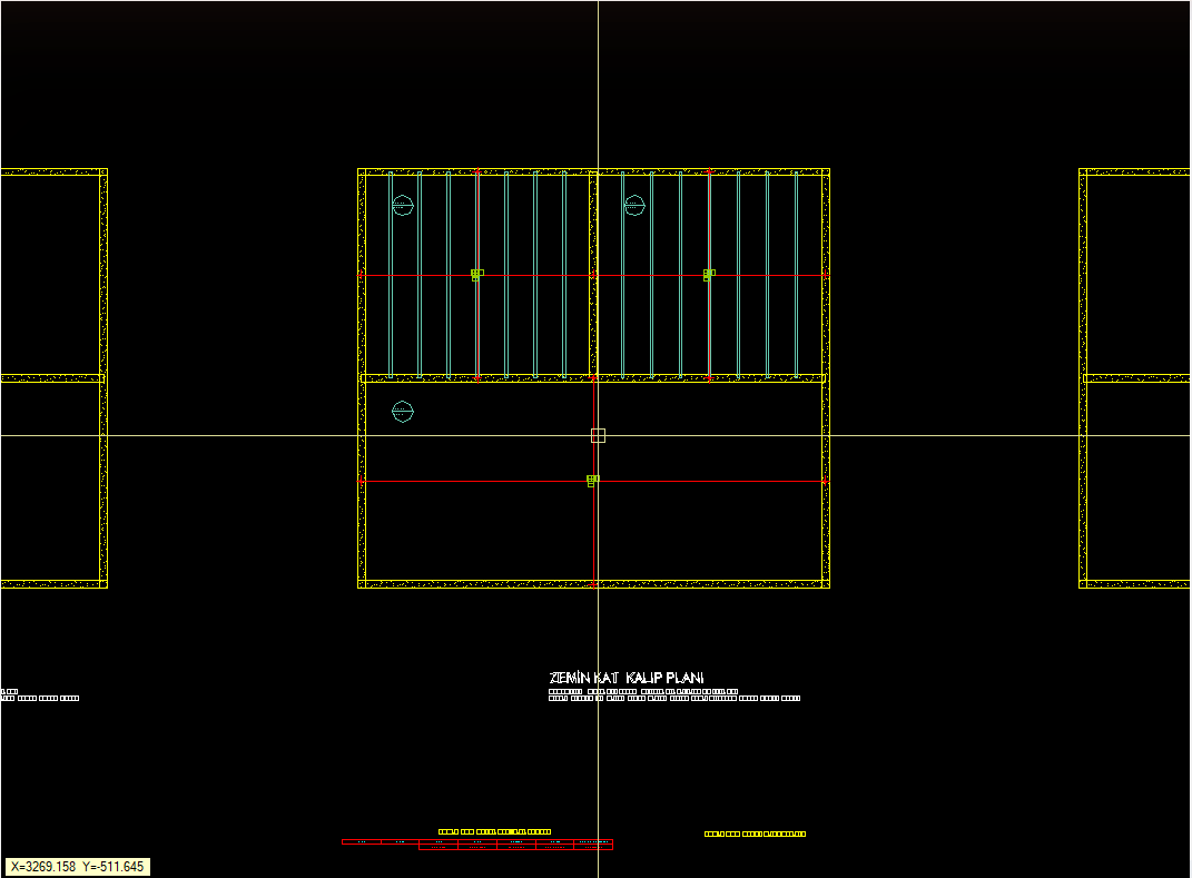
15. Drawings
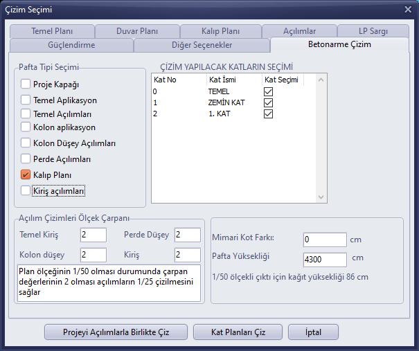
The Drawing button (or Create Drawing in the Static Analysis window) opens the Drawing Selection. Timber slabs are drawn with their timber joists in the formwork plan; reinforced concrete slab reinforcement is not drawn in timber calculation axes. In the example, only Formwork Plan has been ticked in the Reinforced Concrete Drawing tab and Draw Storey Plans has been pressed.
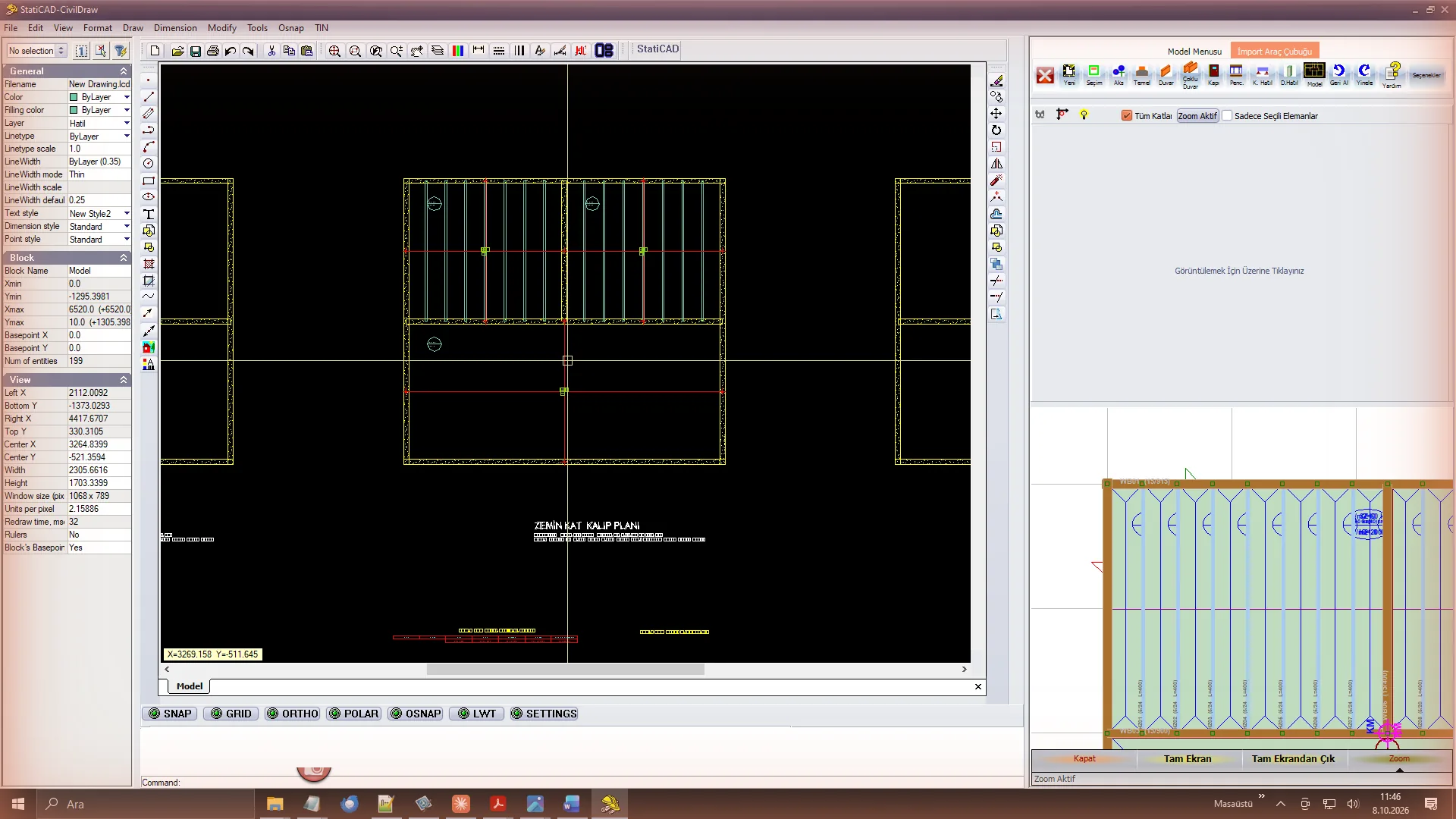

The storey plan page of the report also shows the slabs with their joists and the colour codes for section inadequacy:
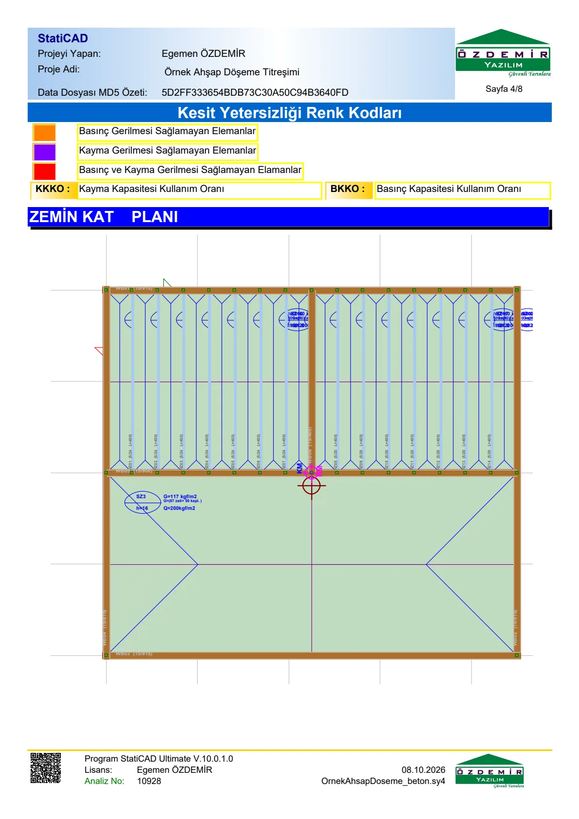
Figure 34 – Report: GROUND FLOOR PLAN (colour codes for section inadequacy)
16. Tips and common situations
- The definition is made on the calculation axis. The Timber Slab tab in the window of the slab piece (ss) only shows a guidance text; in slabs divided into ribs, too, the unit of the check is the original calculation axis.
- The Detect from model button works only while a single calculation axis is being edited; with a multiple selection, the common values in the boxes are written.
- The Joist direction is not definitive if the model finds full-span joists in both directions or finds none; select X/Y in the box.
- Mass difference information: if the vibration mass differs by more than 20% from the slab G in the program, an information row appears. Only permanent actions are used in vibration; enter the finish load realistically (50 kg/m² in the example; the default 175 kg/m² screed/finish load is heavy for a timber slab).
- The composite effect is entered only in the Composite (4.8.2) page, since the model has no fastener information; it is assumed that the boards are full-length or glued end to end in the joist direction (4.8.2 item 3).
- CLT: 7 or more layers require a detailed calculation in the code, and the program reports an input error. If the layer total differs from the slab thickness in the model by more than 5%, a note is added.
- Report selection: a report under Timber Element Reports is also generated when it is ticked on its own.
- Timber shear walls: if the connection stiffnesses are left empty, the program assigns default values and warns with the wall name; enter the values according to the project (Section 5.1).