Timber Building Modelling Recommendations with StatiCAD
A practical step-by-step method that can be used to create grid members (edge studs, intermediate studs, top chord beams, band beams, bottom chord beams) inside timber shear walls is presented at Creating a Grid Inside Selected Walls.
A practical step-by-step method that can be used to create grid members (main beams and horizontal band beams) inside timber slabs is presented at Create Rib/Grid on Selected Slab.
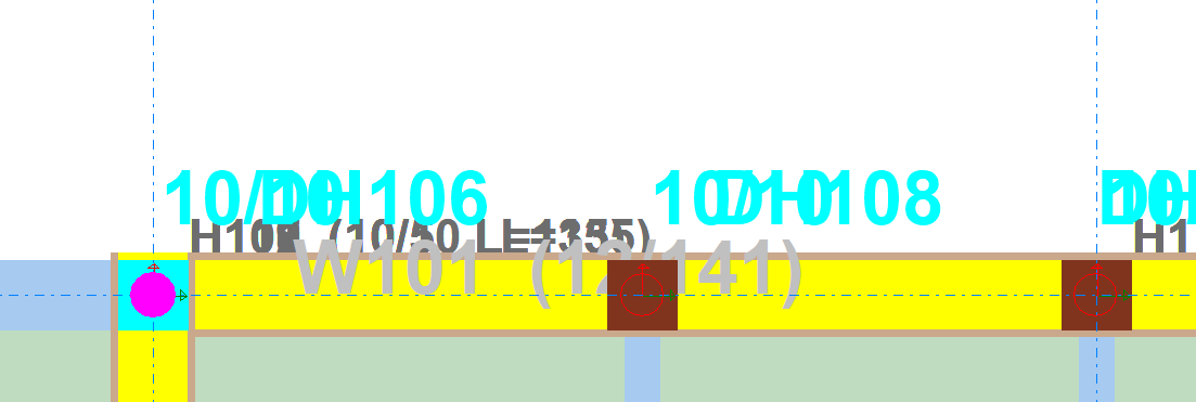
If you have defined members with an eccentricity (i.e. not at their own centroid), uncheck the boxes shown below in the project general settings to ensure that each member is placed at its own centroidal axis in the finite element model. Otherwise, errors may occur because members will be generated at the axis intersection where they were defined.
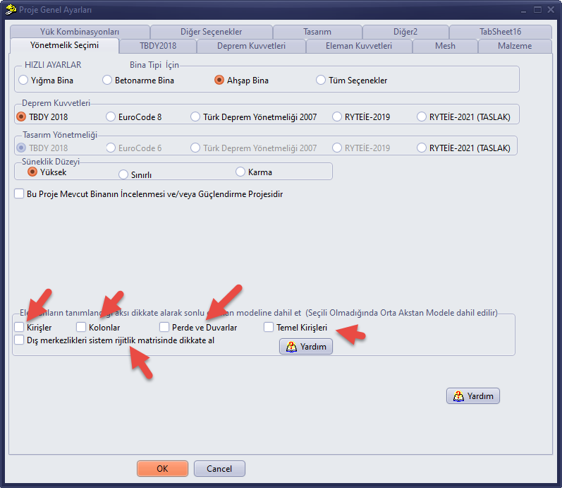
When the options above are in this state, member intersections must be made from the central axes.
Having the main beams inside the slab run in the short direction of the slab, with dimensions of approximately 15 cm width and 30 cm depth, will reduce the number of beam deficiencies after analysis.
Horizontal beams inside walls should be approximately 15 cm wide and 15 cm deep to reduce the number of beam deficiencies after analysis. The depth value can be increased for top chord beams of walls.
It is recommended that secondary beams inside the slab be 10 cm wide and 30 cm deep, running in the long direction.
Care must be taken if hinges are to be used in beam members. Defining a hinge at the supported end of a cantilever or an improperly supported beam may corrupt the finite element model results.
In cantilevered slabs, care must be taken to ensure that the slab grid is extra strong. The strong main beams of the slab should be placed in the short/main cantilever direction.
For wall studs, considering dimensions of at least 15 cm thickness and 20 cm height will reduce the number of deficient members after analysis.
Since timber structures have a large number of structural members, the following measures can be taken in the event of memory problems or excessively long analysis times.
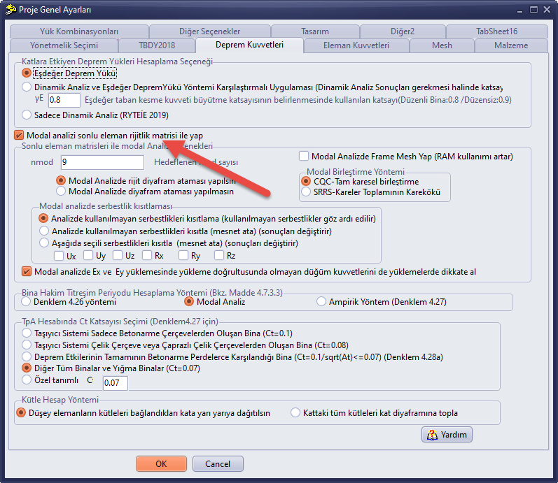
Not performing the modal analysis with stiffness matrices (unchecking the option) reduces analysis time and RAM usage.
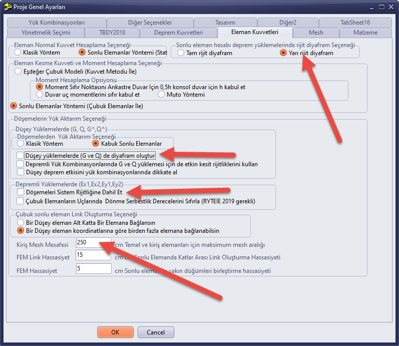
It is recommended to use a semi-rigid diaphragm and not to use a rigid diaphragm for gravity loads.
Excluding slabs from the system stiffness in earthquake load cases reduces analysis time and RAM usage.
Setting the beam mesh spacing to a large value such as 250 cm reduces RAM usage and analysis time. Since beam-beam intersections are typically meshed every 60 cm and beams are already meshed (subdivided into finite elements) at intersections, using a large value does not significantly reduce the accuracy of the model.
In order to perform timber beam design according to TS647, the option "Perform Beam Reinforcement Calculation" must be selected on the Design page of the Project General Settings.