Getting Timber Project Drawings in StatiCAD
In the current version, the program provides the foundation setting-out plan, floor plan, formwork plan, and axis-by-axis elevation details for timber project drawings.
To generate drawings, first run the analysis for your project. After the analysis, check the status of any inadequate members as described at Editing Insufficient Elements in a Timber Building with StatiCAD. To obtain the foundation setting-out plan, floor plan, and formwork plan drawings combined in a single output, click the Generate Drawing and Draw Floor Plans button.
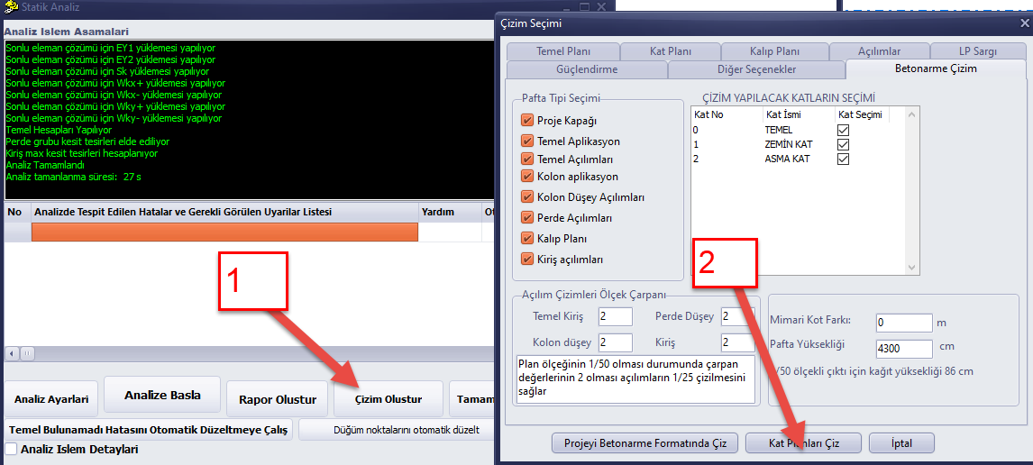
Review the generated drawing. If the level of detail is not as desired, change the options in the Foundation Plan, Floor Plan, and Formwork Plan tabs, then regenerate the drawing using the Draw Floor Plans button again. Save the drawing that you have created and find suitable as a DXF file as described at Saving the Drawing as DXF and Printing with AutoCAD.
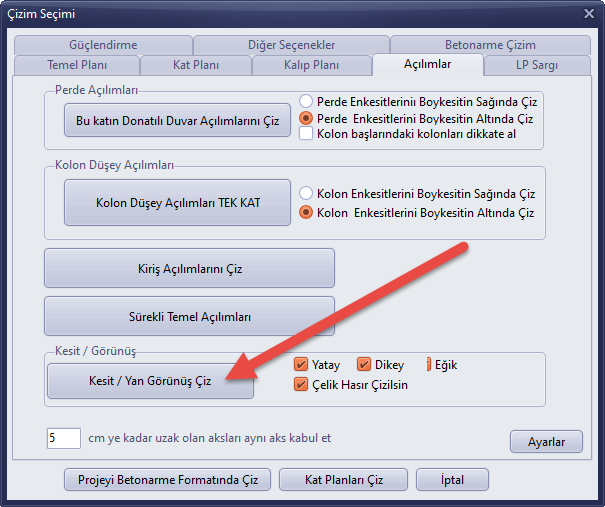
To obtain the axis-by-axis elevations of the building, use the Draw Section / Elevation button in the Elevations tab to view the drawing. Save it as DXF as described in the link above. Combine the drawings from the two files in AutoCAD, StatiCAD-TechnicDraw drawing editor, or any DXF-compatible drawing application.