Automatically Adjusting Roof Sheathing and Post Elevations
This article describes how, in StatiCAD, the roof sheathing (a polygon slab) is built as a triangular mesh from the end elevations of the rafters, purlins, ridge beams and valley rafters, and how the top elevations of the roof posts are set equal to the beam elevations. Both operations are carried out with one command each in the Macros menu.
1. About this article
In timber (or steel) roofs, the sheathing is an inclined surface that rests on the rafters, purlins, ridge beams, valley rafters and hip rafters. In StatiCAD this surface is modelled with a polygon slab. You draw the slab flat over the roof plan without assigning an elevation; the Macros › Mesh polygon slab by beam end elevations (TIN - roof sheathing) macro then discards the flat mesh of the slab, re-triangulates it so that the mesh runs along the beams, and sets every mesh node to the elevation of the beam beneath it at that point. In this way the sheathing shares nodes with the beams, and the loads acting on the sheathing are transferred to the beams in the analysis.
The article also describes the Macros › Set selected post/column top elevations equal to beam elevations macro. This macro sets the top elevation of the posts that carry the roof equal to the elevation of the beam above them at that point.
The descriptions are based on a real timber hip roof model: plan dimensions 69.45 × 19.00 m, sheathing area 1273.31 m², about 600 timber beams (rafters, purlins, ridge, valley, hip) and 63 posts. The numbers shown on screen are the results of this model.
Edition: Both macros are in the Macros menu; there is no edition restriction. The screenshots were taken with StatiCAD Ultimate V.10.0.1.0.
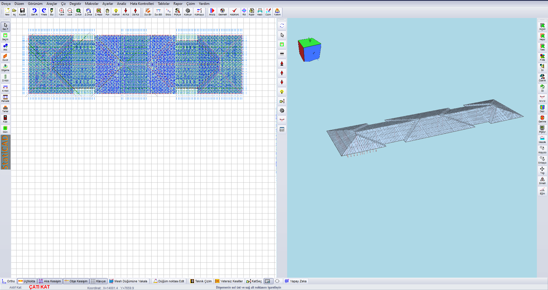
Figure 1 – Main screen after meshing: plan on the left (sheathing triangles and beams), 3D view on the right
2. General workflow
- Draw the roof beams (rafters, purlins, ridge, valley/hip) on the roof storey and assign the top elevation of both ends of every beam (Section 3).
- Place the posts and make their top elevations equal to those of the beams with Macros › Set selected post/column top elevations equal to beam elevations. Delete posts that were drawn twice at the same point (Section 4).
- With Slab Drawing › Polygon, draw a polygon slab that follows the outer perimeter of the roof plan. Do not assign an elevation; the slab is drawn flat at the storey elevation (Section 5).
- Select the slab and run the Macros › Mesh polygon slab by beam end elevations (TIN - roof sheathing) macro; the plan and the 3D view on the split screen refresh automatically (Section 6).
- In the slab properties, enter the real thickness, material and loads of the sheathing (Section 7).
- Check in the 3D view whether the mesh has any kinks; if it has, correct the beam elevations and run the meshing again (Section 8).
- Run the analysis (Section 9).
Order: The mesh is built from the beam elevations at the moment the macro is run. If you change the beam elevations afterwards, run the meshing again; each time, the macro discards the old mesh and builds a new one.
3. Preparation: roof beams and end elevations
The node elevations of the sheathing mesh are taken only from the beams. For this reason, the geometry of the roof must be fully defined by the beam end elevations. Right-click a beam and open its properties: Left Top Elevation is the top elevation of the 1st end of the beam (the end where drawing was started), and Right Top Elevation is that of the 2nd end. Both are given in cm relative to the storey top elevation; the downward direction is negative.
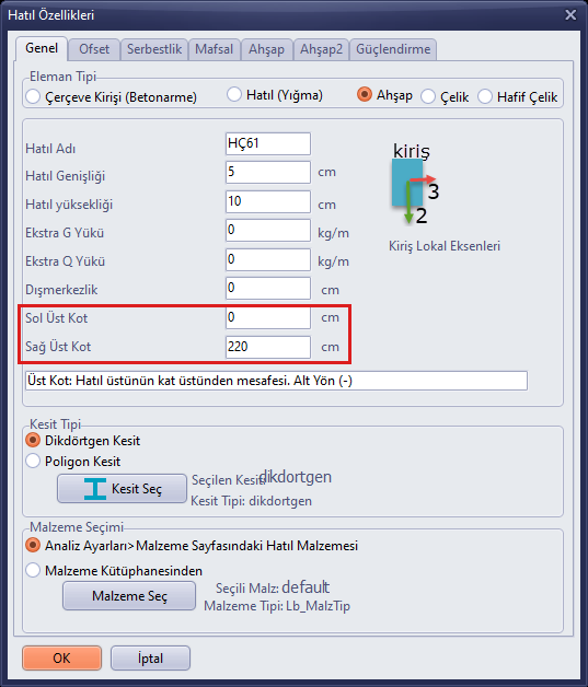
Figure 2 – Bond Beam (Beam) Properties: for a rafter running from the eave to the ridge, Left Top Elevation = 0, Right Top Elevation = 220 cm
- Rafter: the eave end is usually 0 and the ridge end takes the ridge elevation. The elevation varies linearly in between.
- Purlin: since it is horizontal, both of its ends are at the same elevation. This elevation must be equal to the elevation of the rafters that it crosses at that point.
- Ridge beams, valley rafters and hip rafters: the elevations of their ends must be the same as those of the rafters and purlins they join.
- Short (cripple) rafters: the end that terminates at a valley or a hip must take the elevation of the valley/hip rafter at that point. You can assign these elevations in one go with the command described in the article Automatically Adjusting Rafter Elevations to the Hip and Valley Rafters.
Elevation consistency: If two beams intersect in plan, or one ends on the other, their elevations at that point must be the same. Otherwise the mesh node sits on only one of the beams and the sheathing kinks at that point (Section 8). In this case the macro takes the highest elevation among the candidates at the same XY.
4. Setting post and column top elevations equal to the beam elevations
Roof posts carry the ridge, the valleys and the purlins. In the finite element model, the top end of a post must join the beam above it at the same node. For this, the top elevation of the post must be equal to the elevation of the beam at that point. Manually entered top elevations usually differ by a few cm; in the analysis, this difference leaves the post unconnected to the beam.
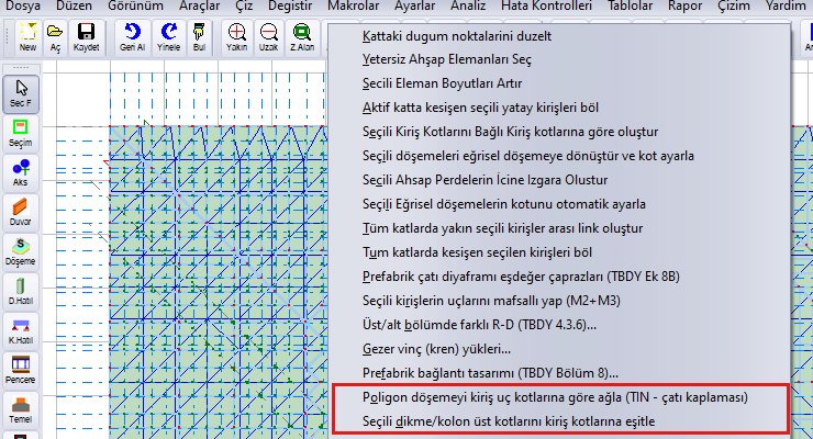
Figure 3 – Macros menu: the roof sheathing and post top elevation macros (the last two items)
4.1 Running the macro
- Make the roof storey the active storey. If you want to correct only some of the posts, select them.
- Click Macros › Set selected post/column top elevations equal to beam elevations.
- If no post is selected, the program asks for confirmation for all the posts on the active storey.
- When the operation finishes, a results window opens. The plan is redrawn; on the split screen the 3D view is refreshed as well.

Figure 4 – Confirmation prompt when no post is selected: all posts on the storey are processed with Yes
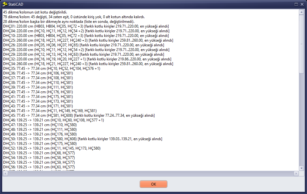
Figure 5 – Results window: summary lines and a scrollable list of posts
The first line gives the number of posts whose top elevation was changed. The second line counts the posts by status. If there are posts drawn at the same point, the third line gives their number. After that, the changed posts (the old -> new elevation and the beams above the post) and the posts at points where beams with different elevations meet are listed, and last of all the posts drawn at the same point.
If the result is short, it is shown in a standard message box; if it is long, it is shown in a window that fits on the screen and can be resized and scrolled. The whole list is in the box in this window; you can select and copy the text.
Table 1 – Post statuses
| Status | Meaning |
|---|---|
| “değişti” (changed) | The top elevation was set equal to the elevation of the beam above it at that point. |
| “zaten eşit” (already equal) | The top elevation was already equal to the beam elevation; it was not changed. |
| “üstünde kiriş yok” (no beam above) | No beam passing through the post point was found; the top elevation was kept. Check the location of the post or the beam. |
| “alt kotun altında kalırdı” (would fall below the bottom elevation) | The beam elevation is below the bottom end of the post (or less than 1 cm above it); the top elevation was kept. |
| “[farklı kotlu kirişler …, en yükseği alındı]” (beams with different elevations …, the highest was taken) | There are several beams with different elevations at the post point (for example, a ridge beam and a ceiling beam). The highest elevation was taken so that the post reaches up to the roof. |
4.2 How is it calculated?
- Post point: the post node in the finite element model. For a rectangular section the midpoint of the section is used, and for a polygon section the centroid.
- Candidate beams: the beams on the same storey whose plan axis is closer to the post point than the larger of the FEM precision and half the beam width.
- Elevation: linear along the beam between the two end elevations. If the post is at the end of the beam, or if both ends of the beam are at the same elevation, the stored value is taken as it is.
- Posts at the same point: if there is more than one post at the same point within the FEM precision, they are listed at the end of the window; they are not changed.
Posts drawn twice at the same place: If the list contains lines such as DHÇ01 = DHÇ10, two posts have been drawn at the same place. Select the extra one and delete it with the Delete key. Because deleting moves the last post into the vacated position, the names of the remaining posts may change. In the example model, 16 of the 79 posts were deleted for this reason.
Undo: The macro saves an undo record before and after the operation. Undo returns to the state before this operation in a single step, and Redo applies the operation again. After the change, the project is considered unsaved and the previous analysis results become invalid.
5. Drawing the sheathing slab
The sheathing is drawn with the Polygon button on the Slab Drawing toolbar. Click the corners in order and close the polygon. Leave the Elevation box at 0: the slab is drawn flat at the storey top elevation. The macro will assign the elevations.

Figure 6 – Slab Drawing toolbar: the Polygon slab and Mesh Settings buttons
- The edges of the polygon must follow the eave line of the roof. Beam segments that fall outside the polygon do not take part in the mesh.
- For concave (L-, T- or U-shaped) roofs, draw the polygon along the outer perimeter. The macro preserves the polygon boundary.
- The flat mesh created during drawing is not important; the macro discards it.
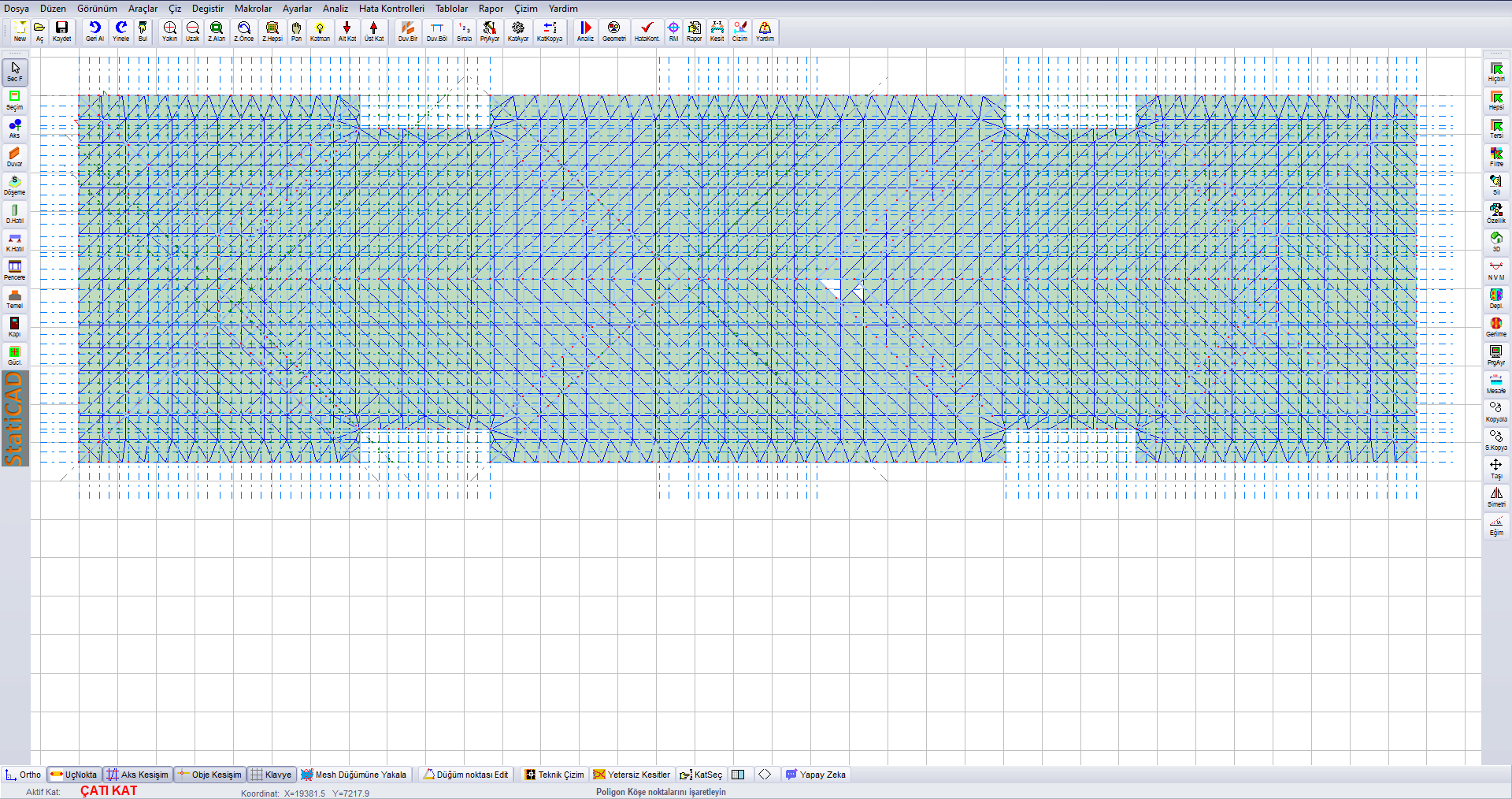
Figure 7 – Plan before meshing: roof beams (blue) and the polygon slab drawn flat over them (green, with the standard triangular mesh)
5.1 Mesh spacing
The maximum spacing of the intermediate nodes that the macro places along the beams is the smaller of the X Direction and Y Direction Max Mesh Width values in the Special Slabs window opened with the Mesh Settings button (default 120 cm). For a denser mesh, reduce this value.
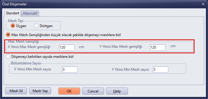
Figure 8 – Special Slabs (Mesh Settings): the Max Mesh Width is the mesh spacing of the macro
Do not use Make Mesh: After the meshing, the Make Mesh button in this window meshes the slab again with the standard method, and the roof mesh is lost. To renew the mesh, always use the Macros › Mesh polygon slab by beam end elevations (TIN - roof sheathing) macro.
6. Meshing the sheathing by the beam end elevations
6.1 Running the macro
- Make the roof storey the active storey. If you want to mesh specific polygon slabs, select them.
- Click Macros › Mesh polygon slab by beam end elevations (TIN - roof sheathing).
- If no polygon slab is selected, the program asks for confirmation for all the polygon slabs on the active storey.
- When the operation finishes, a results window opens. The plan is redrawn; on the split screen the 3D view is also refreshed with the new mesh.
3D window: If the 3D view is open in a separate window rather than on the split screen, update it with the Refresh button at the top left.

Figure 9 – Confirmation prompt when no polygon slab is selected

Figure 10 – Results window: 5096 triangles and 2722 nodes in the example model
Table 2 – Values in the results window
| Value | Meaning |
|---|---|
| “üçgen, düğüm” (triangles, nodes) | The number of triangles and nodes of the new mesh. |
| “kiriş” (beams) | The number of beams that lie inside or on the boundary of the polygon and take part in the mesh. |
| “kiriş ara noktası” (beam intermediate points) | The number of nodes placed on the beam axes at the mesh spacing. |
| “atlanan (kiriş kesişimi)” (skipped, beam intersection) | The number of intermediate points that were not placed because they fall closer than the FEM precision + 1 cm to another beam in 3D. Such a node would divide both beams at once and connect them rigidly in the analysis. |
| “kotu interpolasyonlu” (interpolated elevation) | The number of nodes that do not fall on any beam (corner, edge, fill) and whose elevation is found from the neighbouring nodes. |
| Z … cm | The lowest and highest absolute elevation of the mesh nodes. |
| “çakışan TIN üçgeni atıldı / delik üçgeni eklendi” (overlapping TIN triangles discarded / hole triangles added) | The numbers of triangles repaired during triangulation (see below). |
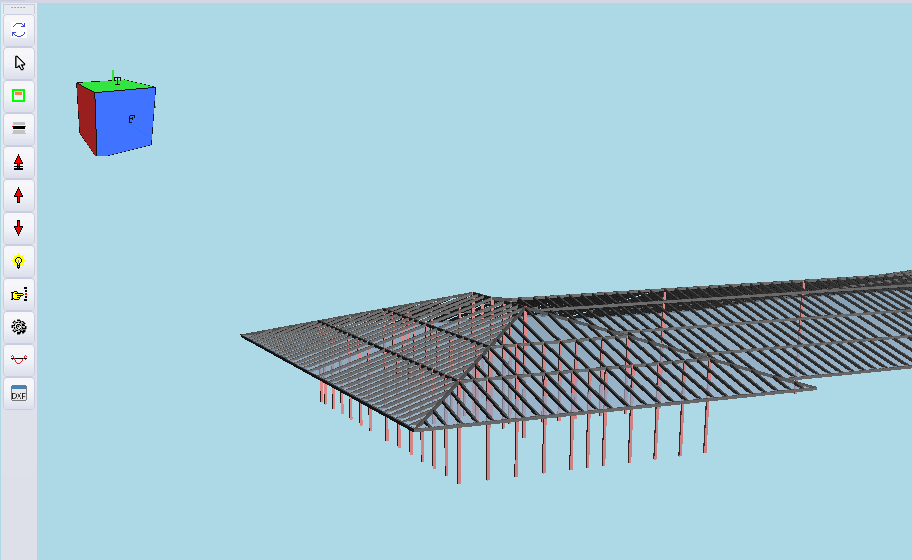
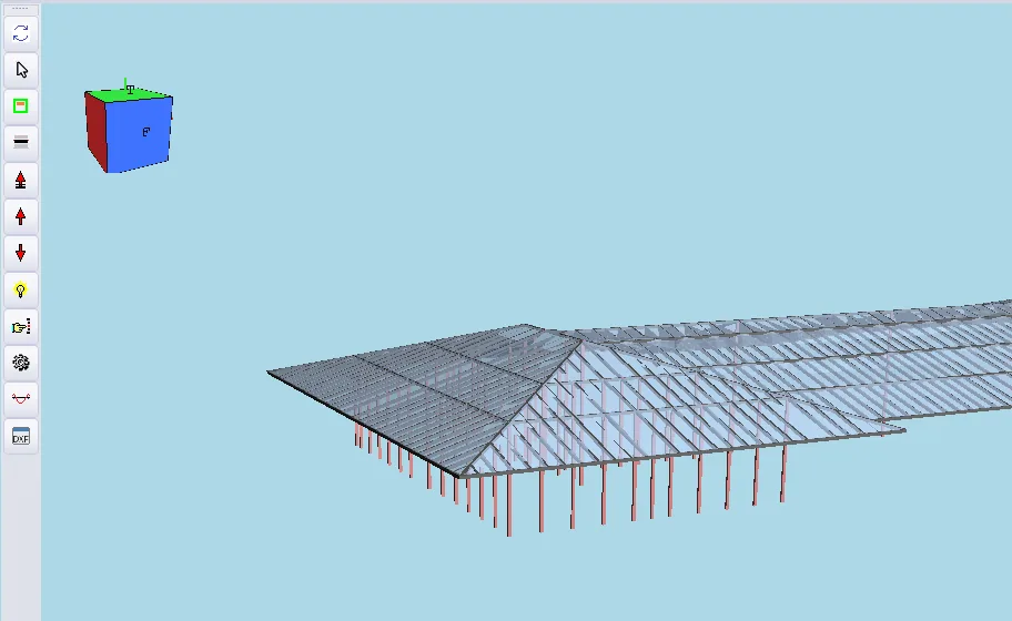
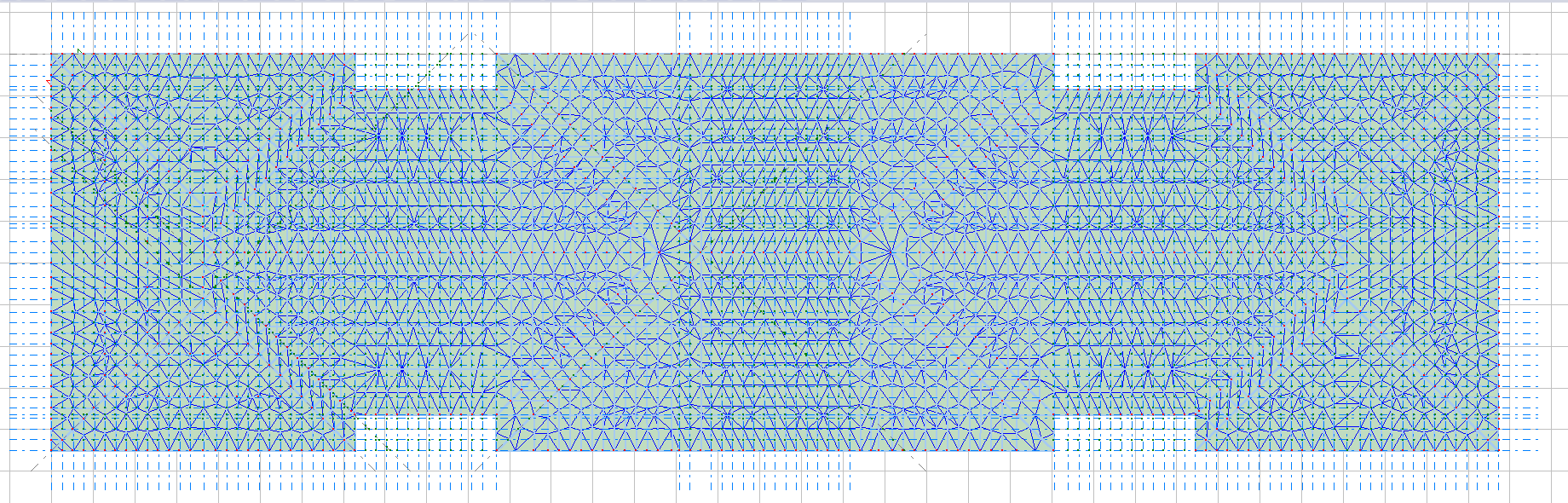
Figure 13 – Plan after meshing: the triangle edges follow the beam axes
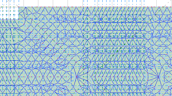
Figure 14 – Plan detail: the nodes are on the beam axes, with fans of triangles where the beams meet
6.2 How is the mesh built?
- Beam ends: every beam end that lies inside the polygon or on its boundary is a node; its elevation is the elevation of that end of the beam (storey top elevation + Left/Right Top Elevation). The points where beams cross the polygon edge also become nodes.
- Beam intermediate points: each beam is divided into segments shorter than the mesh spacing between its ends and the ends of the other beams that terminate on it; the elevation is linear along the beam. Without these points, the triangles would connect the eave nodes on both sides of the ridge directly, and the sheathing would cut through the ridge.
- Polygon boundary: the corners and the nodes on the edges are supplied in order as the triangulation boundary; concave roofs are preserved.
- Fill points: nodes are added at the mesh spacing in large regions left without beams.
- Triangulation: the nodes are triangulated in plan, without taking the elevation into account (TIN, triangulated irregular network).
- Elevations: a node that falls on a beam takes the elevation of the beam; if there is more than one beam at the same point, the highest elevation is taken. The elevation of nodes that do not fall on a beam is found over the mesh as the average (harmonic) of the neighbouring nodes.
In regular (equally spaced) rectangular cells, the triangulation may sometimes place two triangles in the same cell and leave the neighbouring cell empty. The macro filters out these triangles, fills the gaps, and applies the mesh only if every interior edge belongs to exactly two triangles, every boundary edge belongs to a single triangle, and the area covered in plan is within 0.1% of the polygon area. If these checks do not pass, the existing mesh is kept and the reason is written in the results window.
Undo: The macro saves an undo record before and after the operation: Undo returns the mesh to its old state in a single step, and Redo brings the new mesh back. To rebuild the mesh, simply run the macro again. After meshing, the project is considered unsaved and the previous analysis results become invalid.
How is the sheathing connected to the beams? The mesh nodes on the beam axes divide the beams in the analysis. At these nodes the sheathing and the beam share a common node, and the sheathing load is transferred to the beam. Nodes that do not lie on a beam (fill, edge) belong to the sheathing only.
7. Sheathing thickness, material and loads
Right-click the polygon slab and open its properties. The thickness (h) and the material do not affect the mesh; they can be entered before or after meshing. In the analysis, the thickness and self-weight of the sheathing shell are calculated from the h value.
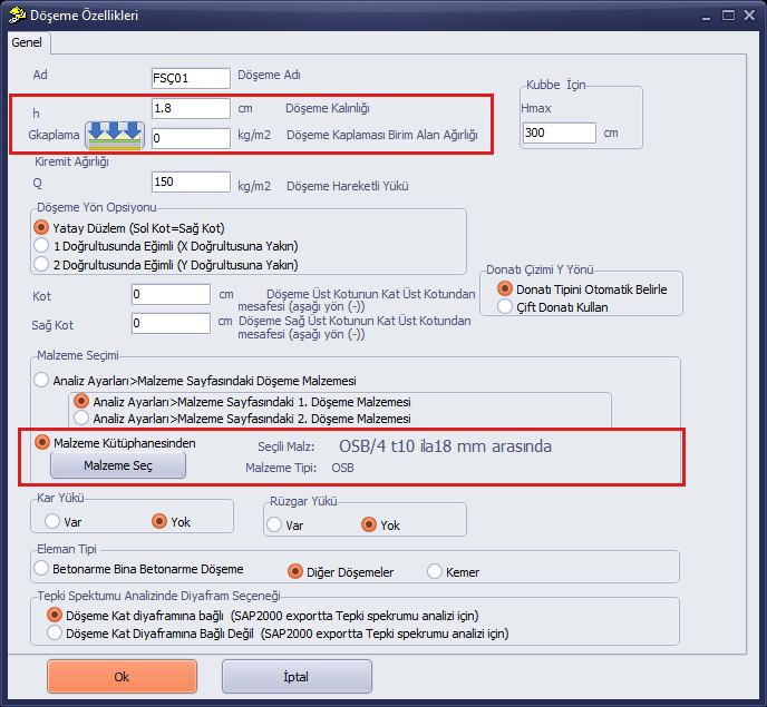
Figure 15 – Slab Properties: 18 mm OSB sheathing in the example model (From Material Library), Q = 150 kg/m²
- h: the real thickness of the sheathing (1.8 cm in the example).
- Material: select the sheathing material with From Material Library (OSB in the example).
- Gkaplama, Q, Snow Load, Wind Load: the loads on the sheathing.
- Do not change the Slab Direction Option and Elevation / Right Elevation fields (Horizontal Plane, 0). The elevations of the mesh are stored at the nodes.
Default 12 cm reinforced concrete sheathing: If the default thickness (12 cm) and reinforced concrete material of the slab drawing toolbar are left unchanged, the inclined sheathing behaves like a folded plate. Because the sheathing is much stiffer than the timber beams, it carries the load itself, and the internal forces of the beams come out much smaller than they really are. In the example model, a rafter moment (M3) of 94 t·cm in the solution without sheathing dropped to 4.4 t·cm with 12 cm reinforced concrete sheathing. Always assign the real thickness and material to the sheathing.
8. Check: elevation consistency and kinks
Because the mesh nodes take the beam elevations exactly, inconsistencies in the beam elevations show up as kinks in the mesh. The most common case is a purlin that lies above or below the rafter plane: the nodes on the purlin take the purlin elevation, the rafter nodes right next to it take the rafter elevation, and the sheathing kinks along the purlin.
Figure 16 – If the purlin elevation differs from the rafter plane by Δ, the sheathing mesh kinks along the purlin (schematic, not to scale)
In the middle section of the example model, 12 purlins were 4.5 cm, 8.7 cm and 13.1 cm above the rafter plane (the purlins had been drawn according to the slope of the end section, and the rafters with a lower slope). The end elevations of the purlins were lowered to the rafter plane in the beam properties (67.10 → 62.58 cm; 128.97 → 120.29 cm; 194.30 → 181.22 cm), the post elevations were matched again, and the meshing was run again.
8.1 Checklist
- Are the elevations at that point the same for beams that intersect or end on one another?
- Are the short rafters connected to the valley and hip rafters at the same elevation? Is there any corner rafter whose two ends are both still at elevation 0?
- Are the purlins in the rafter plane? Is the slope of the ridge beams and valley rafters compatible with the rafters?
- Are there any beams or posts drawn twice at the same place? (Beams drawn on top of each other are deleted automatically at the start of the analysis; for posts see Section 4.)
- After correcting the beam elevations, did you run the post macro and the meshing again?
9. Analysis
With the meshed sheathing, the analysis is run as usual. The example model (about 600 beams, 5000 shell triangles) was solved in about 1.5 minutes.
- At the start of the analysis, beams drawn twice at the same place are deleted automatically; because the last beam takes the place of the deleted beam, some beam names may change. After the analysis, the 3D view refreshes itself once.
- The loads acting on the sheathing are transferred from the sheathing triangles to the common nodes on the beam axes, and from there to the beams and posts.
- After the post macro or the meshing macro, the previous analysis results are considered invalid; run the analysis again.
- If the sheathing material and thickness are not realistic, the internal forces of the beams will be misleading (Section 7).
10. Limitations and tips
- The macro meshes only polygon slabs. It cannot be used for rectangular or quadrilateral slabs.
- Only the beams on the same storey as the slab take part in the mesh. The equivalent braces generated for the precast roof diaphragm do not take part in the mesh.
- Nodes that are closer than the FEM precision in plan are merged. Very short beam segments and beam ends that are very close to each other reduce the quality of the mesh.
- Fill nodes are placed in large empty areas outside the regions where beams are drawn; the elevation of these nodes is found from the neighbouring nodes. So that the sheathing follows the real geometry in regions without beams, draw the beams (rafters) up to the boundary of the polygon.
- If the meshing fails for a slab, the old mesh of that slab is kept and the other slabs continue to be meshed.
- If you have changed the beam or post elevations, run the post macro and the meshing again, in this order.
The inputs in the example are for illustration purposes only; the accuracy of the beam geometry, the sheathing material and the loads is the responsibility of the engineer in charge of the project.