Steel Connection Design
1. About this article
This article explains the connection design in the heavy steel module of StatiCAD: brace end connections, beam end connections (pinned and moment), column bases and the connection detail sheet. In turn it gives where each connection type is defined, which quantities are entered, which checks the program performs and with which assumptions it works. For a step-by-step example see the article Worked Example: Concentrically Braced Steel Frame.
Version: Connection design is available in the versions in which the heavy steel features are enabled (Ultimate and Hybrid); in other versions no connection calculation is made. In the demo version, the calculation rows and detail drawing of only the first 3 connections (beam / brace ends and column bases together) are given. This article was written for version V.10.1.2.0.
Table 1 – Connection types
| Code | Connection | Where used | Basis |
|---|---|---|---|
| CB1 | Slotted box / pipe brace, welded to the gusset plate | Brace end | ÇYTHYE 13; TBDY 9.6.6 / 9.7.5 |
| CB2 | Angle / channel brace, bolted to the gusset plate | Brace end | ÇYTHYE 13 |
| CB3 | I / H brace, bolted through the flanges with four connection angles | Brace end | ÇYTHYE 13 |
| KB1 | Single shear plate | Pinned beam end | ÇYTHYE 13 |
| KB2 | Double angle, bolted | Pinned beam end | ÇYTHYE 13 |
| KB3 | End plate (partial depth) | Pinned beam end | ÇYTHYE 13 |
| KM1 | Extended end plate, bolted | Moment beam end | TBDY Annex 9B.2 |
| KM2 | Bolted flange plate | Moment beam end | TBDY Annex 9B.3 |
| KM3 | Complete-joint-penetration groove weld | Moment beam end | TBDY Annex 9B.4 |
| KA1 | Base plate and anchor rods | Column base | ÇYTHYE 13.7 / 13.8 |
2. General principles
2.1 Where a connection is defined
Each connection family has a project default and, if desired, can be customised for a single member.
- Project defaults: next to the Steel Connection Design (ÇYTHYE 13) box on the Project General Settings > Code Selection tab there are two buttons. "Brace connection…" opens the default for brace ends. The "Beam / column base ▾" button opens a menu: Beam end – pinned (KB1 – KB3), Beam end – moment (KM1 – KM3) and Column base (KA1).
- Member-specific: the "End connection…" button in the beam properties edits the left and right ends of that beam (or brace) separately: "use project default", "specific to this end" or "no connection". For a column base, the column is selected from the Scope list of the column base window.
The program determines which default is applied to a beam end: the pinned beam end default is applied to beams with a pinned end, and the moment default to beams with a moment-transferring (unpinned) end that are connected to a steel column on the same storey.
2.2 Undefined and inadequate connections
- An undefined connection does not affect the member. If the default is left "undefined", that family is not checked; the member result does not change.
- An inadequate connection makes the member "Inadequate". At the end of the analysis, members with inadequate connections are listed in the warning list with their largest ratios.
- Out-of-scope cases (the type does not suit the section, a moment type assigned to a pinned end, the beam connected to a column web) are reported with a separate information line; the member result is not affected.
2.3 Permitted ratio
The "Ratio ≤" value in the same box (default 0.90) is the largest demand / capacity ratio permitted in all connection checks; it leaves a margin so that the connection is not exhausted before the member. Geometry conditions (minimum edge distance, spacing, weld thickness, table limits) are independent of the ratio: if they are not satisfied, the connection is considered inadequate and a "geometry" note appears in the warning.
2.4 Window layout
All connection windows have the same layout: inputs on the left, a scaled diagram at the top right, and below it the check table (limit state, demand, capacity, ratio). When you change a value, the table and the diagram are refreshed immediately; the demands are taken from the last analysis. If no analysis has been run, only the geometry and capacities are shown. In the project default windows, the bottom row gives a summary of all members that use the default (how many are inadequate, the largest ratio).
3. Brace end connections (CB1 – CB3)
The connection of the brace to the gusset plate and of the plate to the beam / column is checked. CB1 is the connection where a slotted box or pipe brace is connected to the gusset plate with four longitudinal fillet welds; CB2 is where a single angle or channel brace is bolted to the plate; CB3 is where an I / H brace is bolted to the plate through its two flanges with four connection angles. When "By brace full capacity" is ticked, the demand is the expected capacity of the brace (TBDY 9.6.6); if it is unticked, the D·E forces are used. For details and verification by hand, see Section 7.8 of the worked example.
4. Pinned beam end connections (KB1 – KB3)
These are the shear connections of steel beams with pinned ends (beam-to-column or beam-to-beam). The demand is the shear force in the envelope of the load combinations and (in braced span beams) the axial force.
4.1 KB1 – single shear plate
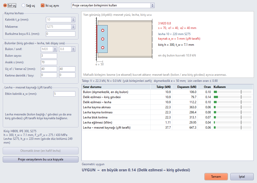
Figure 1 – KB1: beam end with a single shear plate
The plate is connected to the support (column flange / web or main beam web) with a double-sided fillet weld, and to the beam web with a single vertical row of bolts.
Inputs: plate thickness and material; bolt diameter and grade; number of bolts; spacing s; end distance e1 and edge distance e2; weld thickness aw; in a beam-to-beam connection, the depth and length of the top flange cope.
Checks: bolt group (with the eccentricity between the weld line and the bolt axis, the outermost bolt), bearing at the holes in the beam web and in the plate, shear yielding in the plate, shear rupture, block shear rupture and bending, plate–support weld; if there is a cope, shear in the coped web, block shear rupture and bending in the cope section.
4.2 KB2 – double angle
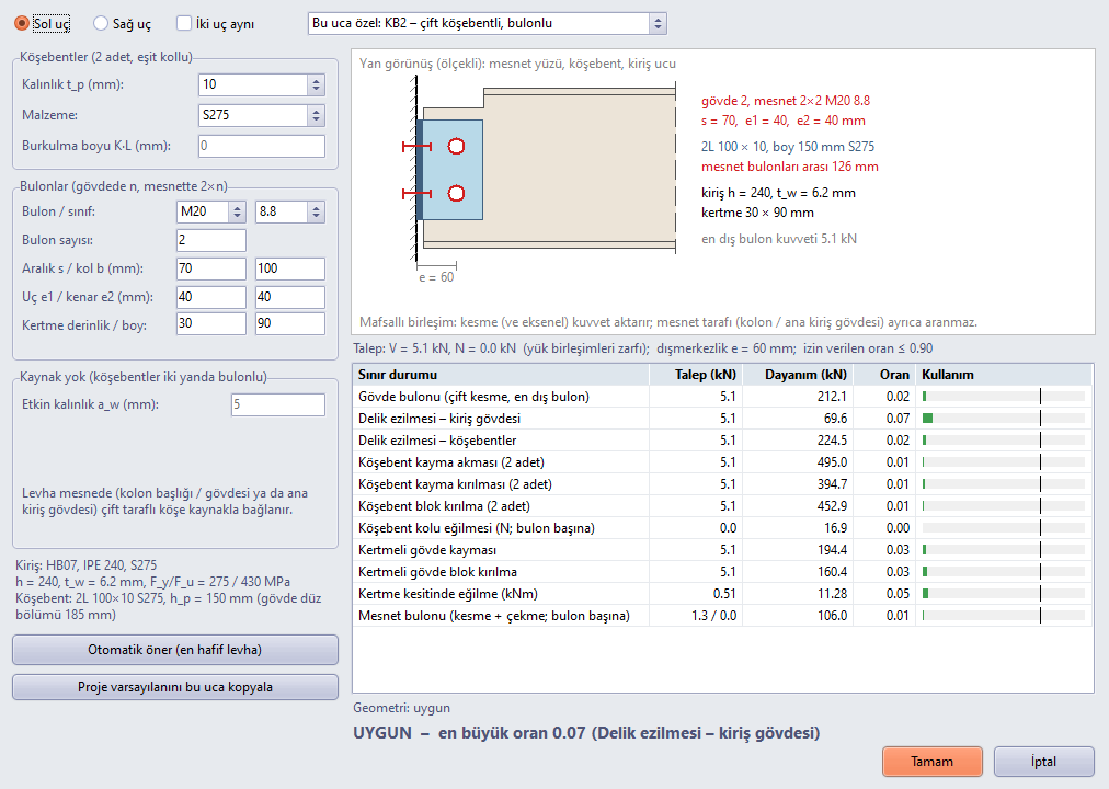
Figure 2 – KB2: beam end with a double angle (coped example)
Two equal-leg angles are connected to the beam web with n bolts (double shear) and to the support with 2×n bolts; there is no weld. The second box in the "Spacing s / leg b" row is the angle leg length; the thickness box is the angle thickness.
In addition to the KB1 checks, the support bolts (combined shear + tension effect) and, if there is axial force, bending of the angle leg are checked. The eccentricity in the web bolts (bolt axis – support face) is taken into account; this is an assumption on the safe side.
4.3 KB3 – end plate
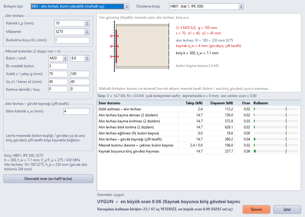
Figure 3 – KB3: beam end with an end plate
A partial-depth plate is connected to the beam web with a double-sided fillet weld and to the support with two vertical rows of bolts (horizontal spacing g). The plate width is taken as g + 2·e2. In addition to the support bolt and plate bending checks of KB2, shear of the beam web along the weld is checked.
4.4 Auto-suggest
The "Auto-suggest" button, keeping the selected type, looks for the connection with the fewest bolts and the thinnest plate that holds at all beam ends using the default (bolt diameter, number, spacing, plate / angle size, weld thickness). The result is written into the boxes and can be changed by hand.
Note: In pinned beam end connections, the support side (column web, main beam web) is not checked separately. No upper limit on thickness is checked for the rotational flexibility of the end plate.
5. Moment beam end connections (KM1 – KM3)
These are the beam-to-column connection details of moment frames given in TBDY 2018 Annex 9B. Only the ends where an I / H beam is connected to the flange of an I / H column (in the direction of the strong axis of the column) are checked.
5.1 Demand
The connection is designed for the expected plastic moment of the beam (Annex 9B.1.4):
- Mpr = Cpr·Ry·Fy·Wp; Cpr = (Fy + Fu) / 2Fy ≤ 1.2, and 1.4 in a welded connection (KM3).
- The distance ℓh of the plastic hinge from the column face is taken from the Annex 9B tables according to the type.
- Vuc = (number of hinges)·Mpr / (span between hinges) + shear from vertical load; at the column face Muc = Mpr + Vuc·ℓh.
- Resistance factors: 1.00 for ductile limit states, 0.90 for non-ductile ones (Annex 9B.1.4).
5.2 KM1 – extended end plate
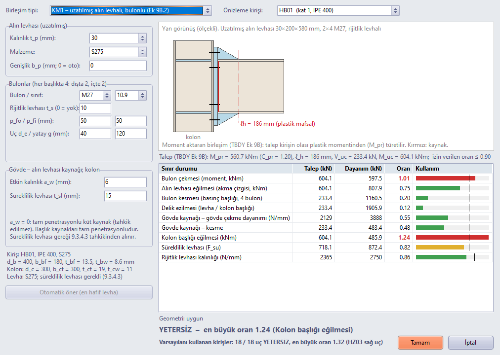
Figure 4 – KM1: moment connection with an extended end plate (project default window)
There are four bolts at each flange (two outside the flange, two inside). If "Stiffener plate ts" is greater than zero, the connection with a stiffener plate is checked; if zero, the connection without a stiffener plate.
Inputs: end plate thickness, width (0: automatic) and material; bolt diameter and grade; pfo and pfi (from the outer / inner face of the flange to the bolt row); end distance de; horizontal bolt spacing g; web–end plate weld aw (0: complete penetration); column continuity plate thickness tsl (0: none).
Checks: bolt tension, end plate bending (yield line), shear in the extended part in a connection without a stiffener plate, shear and bearing at the holes in the bolts at the compression flange, web weld, column flange bending; if there is no continuity plate, local yielding, buckling and crippling in the column web; if there is, the force carried by the continuity plate.
5.3 KM2 – bolted flange plate
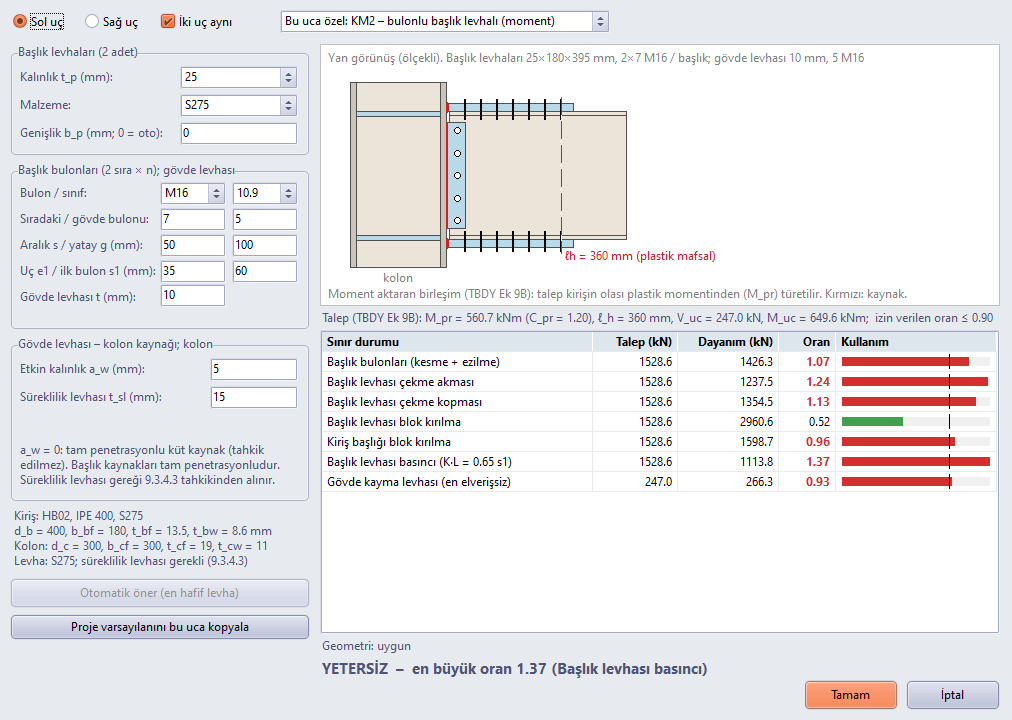
Figure 5 – KM2: moment connection with bolted flange plates (member-specific)
The flange plates are connected to the column flange with a complete-joint-penetration groove weld and to the beam flange with two rows of bolts; at the web there is a single shear plate with one row of bolts.
Inputs: flange plate thickness and width (0: beam flange); number of flange bolts in a row and number of web bolts; spacing s and horizontal spacing g; end distance e1 and distance s1 from the column face to the first bolt; web plate thickness; web plate–column weld aw; tsl.
Checks: flange bolts (shear + bearing), tensile yielding, rupture, block shear rupture and compression in the flange plate, block shear rupture in the beam flange, web shear plate; and also the maximum bolt diameter condition in Eq.(9B.3).
5.4 KM3 – complete-joint-penetration groove weld
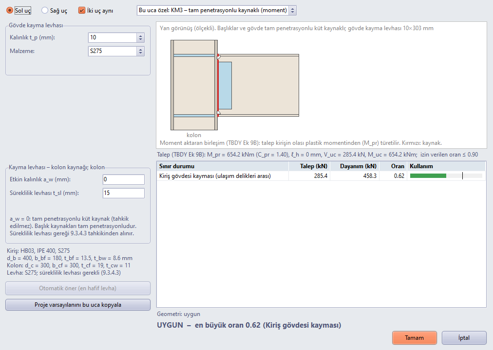
Figure 6 – KM3: moment connection with complete-joint-penetration groove welds
The beam flanges and web are connected to the column flange with complete-joint-penetration groove welds. The thickness of the web shear plate cannot be less than the beam web (9B.4.7a); the strength of the plate–column weld is checked with the condition of 9B.4.7(b) (aw = 0: complete penetration, not checked); shear of the beam web between the weld access holes is checked.
5.5 Application limits and continuity plate
The application limits in Annex 9B Tables 9B.1 – 9B.3 (plate thickness and width, bolt spacings, beam depth and flange thickness, column depth, span / depth ratio, bolt grade) are checked; a quantity outside the limit is shown in the "Geometry" row with the note "outside table limits" and the connection is considered inadequate. If TBDY 9.3.4.3 requires a continuity plate and tsl is not defined, the connection is also considered inadequate.
Scope: If the beam is connected to the web of the column (weak axis), the end is reported as "out of scope". In a box column, KM2 and KM3 are checked without the column side; KM1 is out of scope. There is no end plate with eight bolts and no reduced beam section connection (9B.5). The panel zone is not checked within the connection; it is given in the TBDY 9.3.4.2 row of the column report.
5.6 Auto-suggest
The "Auto-suggest" button, keeping the selected type, looks for the lightest connection that holds at all moment ends using the record. Search order: continuity plate thickness → (KM1) stiffener plate → bolt diameter → (KM2) number of bolts → plate thickness → bolt spacing g → web shear plate and weld. In KM3 only the shear plate, weld and continuity plate are searched. The result is written into the boxes and can be changed by hand.
If no solution is found: The search changes only the connection dimensions; it does not touch the beam and column sections. If the column flange is thin or narrow (e.g. connecting an IPE 400 beam to an HEB 300 column with KM1), no plate / bolt combination passes; the window shows the note "no solution found" and the boxes do not change. In this case the column section must be enlarged or the connection type changed (KM3 does not check column flange bending). In KM2, Eq.(9B.3) limits the bolt diameter according to the beam flange width; in beams with narrow flanges (e.g. at most M16 in S275 IPE 400), the flange bolts and the web shear plate with a single row of bolts are often not enough and the suggestion finds no solution.
6. Column base (KA1)
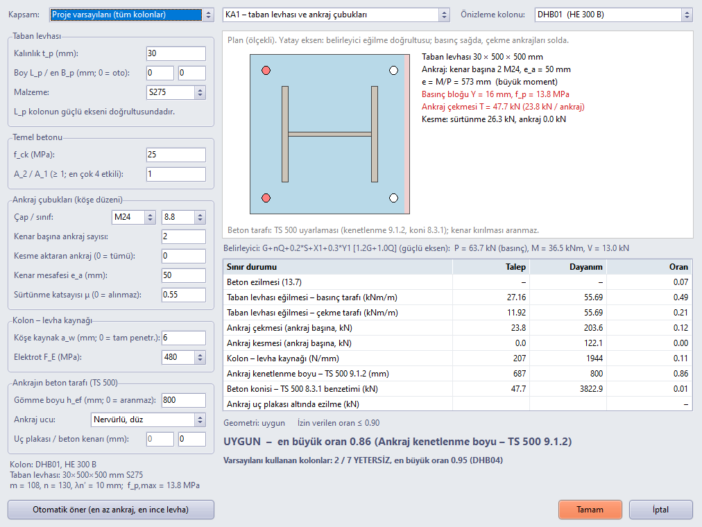
Figure 7 – Column base window: project default
The base plate and anchor rods of I / H, box and pipe section steel columns on the foundation storey are checked. The window opens via Project General Settings > Beam / column base ▾ > Column base (KA1).
6.1 Scope and inputs
When "Project default" is selected in the Scope list, the values entered are applied to all columns that are not customised; the "Preview column" determines with which column's forces the table and diagram are calculated. When a column is selected from the list, "use project default", "specific to this column" or "no column base" is selected for that column in the box next to it.
Table 2 – Column base inputs
| Input | Description |
|---|---|
| Thickness tp | Base plate thickness |
| Length Lp / width Bp | Lp is in the direction of the strong axis of the column. 0: automatic (column dimension + 4·ea) |
| fck, A2/A1 | Foundation concrete strength and the ratio of the concrete surface larger than the plate (increases the bearing strength; at most 4 is effective) |
| Diameter / grade, anchors per edge | The anchors are in a corner arrangement; the number per edge is the same in both directions |
| Shear-carrying anchors | Number of anchors assumed to carry the shear (0: all). In a plate with large holes, not all anchors may work at the same time |
| Edge distance ea | Distance of the anchor axis to the plate edge |
| Friction coefficient μ | Shear carried by base friction in a column under compression (0: not taken; grout 0.55, concrete 0.70) |
| Fillet weld aw | Column–plate weld (0: complete penetration, not checked) |
| Embedment length hef | Length of the anchor in the concrete. 0: concrete side not checked |
| Anchor end | Straight, hooked or with plate / nut |
| End plate bh | Side of the square end plate in a plated anchor |
| Foundation edge ck | Distance from the anchor axis to the nearest foundation edge (0: unlimited). Limits the cone perimeter |
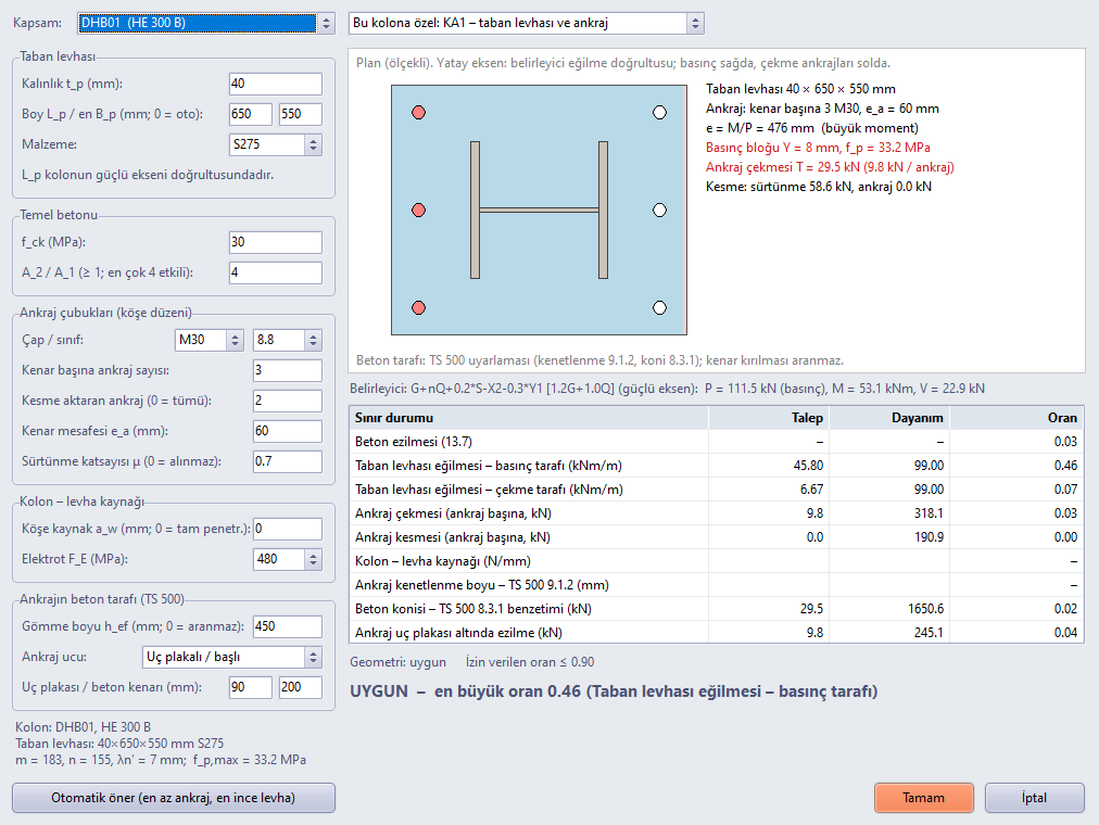
Figure 8 – Column base window: column-specific record
6.2 Checks and method
The demand is the simultaneous axial force, moments and shear of each load combination at the bottom end of the column. Each combination is checked separately about the strong and weak axes of the column; the most unfavourable result is shown (the table gives the governing combination and axis).
- Concrete bearing (ÇYTHYE 13.7): 0.85·fck·A1·√(A2/A1), φ = 0.65.
- Base plate bending: on the compression side, the cantilever of the plate projecting outside the column; on the tension side, between the anchor and the column flange.
- Anchor tension and shear (ÇYTHYE 13.8 → 13.3.9, combined effect). When the eccentricity is small, no tension develops in the anchors; it develops under a large moment or when the column is in tension.
- Column–plate weld.
- Geometry: minimum edge distance, anchor spacing, the anchors lying outside the column section, minimum weld thickness.
6.3 Concrete side of the anchor (TS 500)
When the embedment length hef is entered, the strength of the anchor in the concrete is also checked. The design strengths are taken as fctd = 0.35·√fck / 1.5 and fyd = Fyb / 1.15.
- Development (straight and hooked anchors; TS 500 Article 9.1.2): lb = 0.12·(fyd / fctd)·φ ≥ 20φ; if φ > 32 mm, increased by 100 / (132 − φ). A straight-ended anchor is treated like a ribbed (threaded along its length) bar, a hooked anchor like a plain bar; for a hooked one lb is increased by a factor of 1.5. The required length is reduced by the ratio of the tension force in the anchor to the yield force (at least lb / 2 and 20φ). Ratio = required length / hef.
- Concrete cone (plated anchor; analogy with TS 500 Article 8.3.1 punching): the total tension of the anchor group on the tension side is compared with the strength Vpr = fctd·up·hef using the perimeter up at a distance hef / 2 from the end plates. The foundation edge ck limits the perimeter.
- End plate bearing (plated anchor; ÇYTHYE 13.7): concrete bearing on the net area of the plate.
Adaptation: TS 500 has no separate article for anchor rods. The checks here are an adaptation of the rebar development and punching rules to the anchor; this is also stated in the report row. Edge breakout of the anchor group under shear, side-face blowout and force transfer to the foundation reinforcement are not checked; for anchors close to an edge or with high tension they must be evaluated separately.
6.4 Auto-suggest
"Auto-suggest" looks for the solution that holds at all columns using the record: anchors per edge → anchor diameter → plate thickness → edge distance → weld → (if hef is defined) the shortest sufficient embedment length. The plate length / width are left automatic (0). The result is written into the boxes and can be changed by hand.
Not checked: Shear keys, biaxial bending interaction and column bases other than on the foundation storey are outside the scope. If the name of a column is changed, the column-specific column base record of that column no longer matches and the column returns to the project default.
7. Calculation report
The connection results are added to the steel member reports: on beam and brace pages a connection row for each end (type, dimensions, demand, the ratio of all limit states, geometry status, SUITABLE / X), and on the column page a column base row. In members with identical ends, a single row is written. Ratios exceeding the limit are shown in red.
8. Connection detail sheet
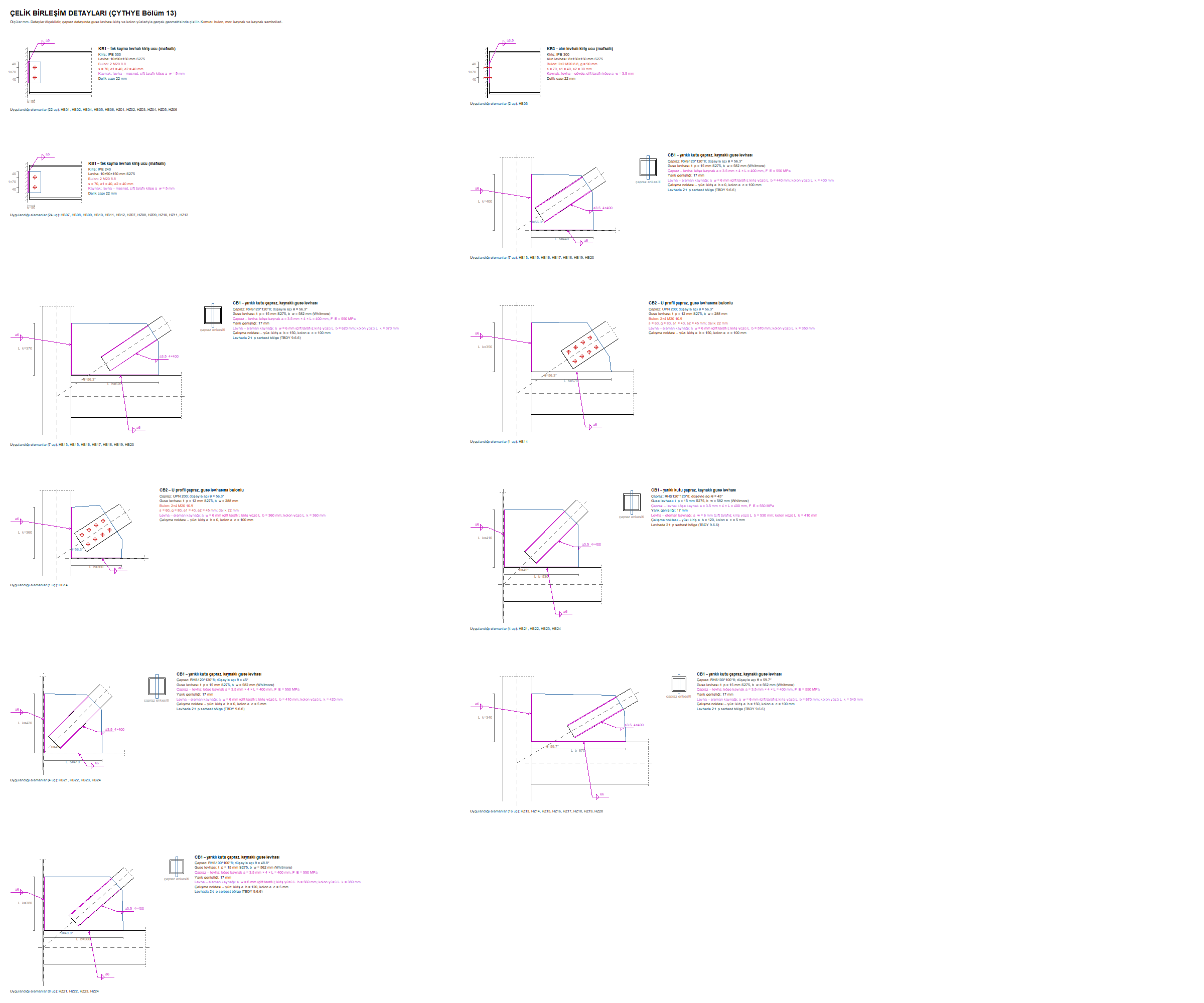
Figure 9 – Detail sheet: brace end and pinned beam end details
The "Draw Steel Connection Detail Sheet" command in the right-click menu on the model screen (with a member selected or on an empty area) opens a new drawing on the drawing screen and draws the details of all connections checked in the last analysis. Ends with the same dimensions are collected in a single detail; under each detail the members it applies to are written. The detail contains the member, plate / angle, bolt pattern, welds, dimensions and a legend column. The column base is drawn in plan and side view.
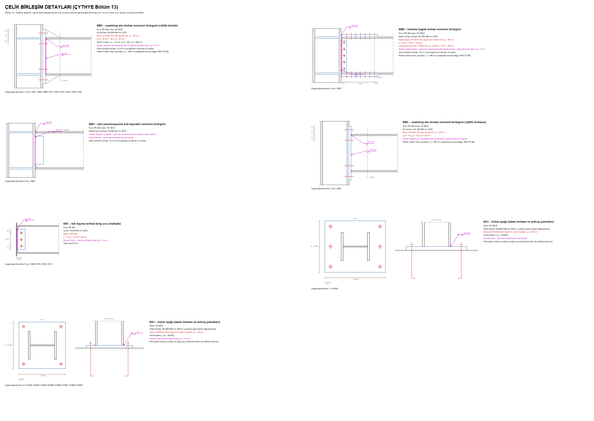
Figure 10 – Detail sheet: moment beam ends and column bases
Drawing rules: The details are drawn to scale. Brace ends connected to a column–beam corner (CB1, CB2) are drawn with the real corner geometry: the column and beam faces, the brace angle θ, the polygon of the gusset plate and the edge lengths Lb / Lk on the two faces. Nodes with a different angle or edge lengths become separate details. The welds carry a weld symbol: a triangle and the a dimension for a fillet weld, a V mark for a complete-joint-penetration groove weld. Welds are drawn with a purple double line and bolts in red; the CelikBulon and CelikKaynak layers are opened for them. The sheet is not drawn if no analysis has been run or if there is no checked connection.
9. Assumptions and known limits
- For moment connections, TBDY Annex 9B gives only the scope, the resistance factors, the expected plastic moment, the plastic hinge location and the application limits; the limit state relations are taken from the ANSI/AISC 358 steps on which Annex 9B is based.
- In the column base, ÇYTHYE gives only concrete bearing and the tension + shear check of the anchor; the base plate sizing is by the AISC Design Guide 1 rectangular stress block method.
- The concrete side of the anchor is checked with an adaptation of the TS 500 rules and only when the embedment length is entered (Section 6.3).
- In a pinned beam end, the support side is not checked (Section 4.4).
- In the detail sheet, the weld symbols are simplified (no distinction between site / shop welds, no weld-all-around mark); in CB3 and beam end details the support is schematic.
- The connection results belong to the last analysis; when the connection or the model is changed, the analysis must be repeated.
Responsibility: The suitability of the connection details for fabrication and erection conditions, the weld qualities and local application rules must be evaluated separately by the responsible engineer of the project.