Masonry Building Retrofit in StatiCAD
Masonry Building Retrofit in StatiCAD
Available Retrofit Types
1-Strengthening with shotcrete
2-Strengthening by adding vertical bond beams to the system
3-Strengthening with fiber-reinforced polymer (FRP) wrapping
4-Strengthening by adding new walls to the system
…
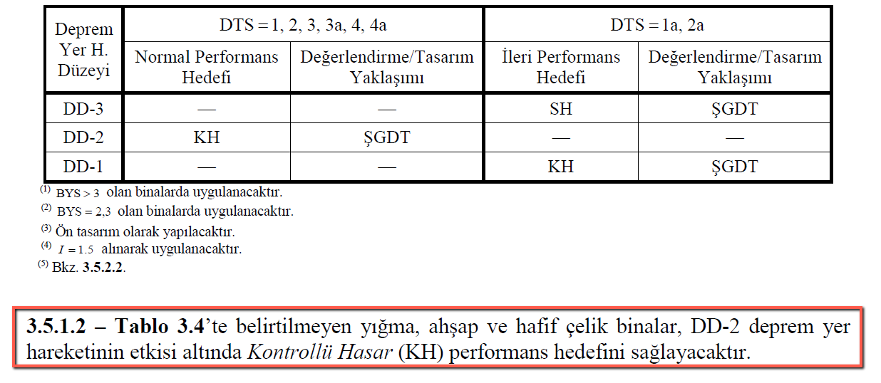
For masonry buildings, the R, D, I coefficients must be taken according to Chapter 11. However, the program applies the values provided by the user.

Analysis must be performed for the DD-2 earthquake ground motion level and the controlled damage performance objective must be satisfied. For school-type buildings, a building importance factor of 1.5 is appropriate.
Since wall safety factors apply to an existing building, a value of 1 is appropriate.
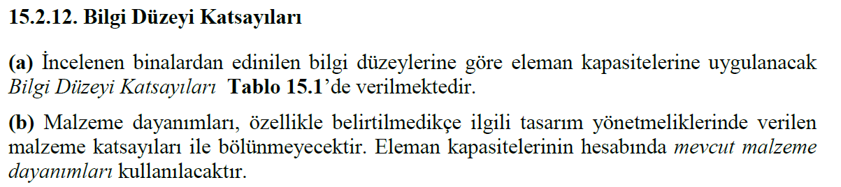
Data collection from the building is carried out as follows in accordance with TBDY2018.
15.2.10. Limited Information Level for Masonry Buildings
15.2.10.1 – Building Geometry: If architectural drawings are available, a visual inspection of the building shall be performed to verify that the existing geometry conforms to the drawings. If no architectural drawings are available, a structural survey of the building shall be obtained. The information gathered shall include the location, lengths, thicknesses, and openings of masonry walls at each storey, as well as storey heights.
15.2.10.2 – Details: The type of roof and slab, their connection details to walls, and the condition of bond beams and lintels shall be determined visually.
15.2.10.3 – Material Properties: The type of wall materials shall be determined visually by removing the plaster from a portion of the wall surface. In structural capacity calculations, the wall shear strengths given in Chapter 11 for each wall type shall be used as the basis.
15.2.11. Comprehensive Information Level for Masonry Buildings
15.2.11.1 – Building Geometry: A structural survey of the building shall be carried out. The information gathered shall include the location, lengths, thicknesses, and openings of masonry walls at each storey, as well as storey heights. The foundation system shall be determined by means of an inspection pit opened outside the building.
15.2.11.2 – Details: The type of roof and slab, their connection details to walls, and the condition of bond beams and lintels shall be examined visually. As a result of this examination, it shall be determined whether rigid diaphragm behavior is achieved at each storey. If this behavior cannot be achieved, the building shall be deemed inadequate in terms of earthquake safety.
15.2.11.3 – Material Properties: The type of wall materials shall be determined visually by removing the plaster from a portion of the wall surface. To determine wall material properties, at least two wall specimen samples shall be taken from the building, and the average properties obtained from compression strength tests of these samples shall be used in calculations performed in accordance with Chapter 11.
In structural capacity calculations, the wall shear strengths given in Chapter 11 for each wall type shall be used as the basis.
.
1-Strengthening with Shotcrete
1.1 A steel mesh of the calculated grade is placed on one or both faces of the wall. The steel mesh is anchored to the existing wall to ensure composite action. The wall is coated with shotcrete or repair mortar of the calculated thickness that provides the design strength.
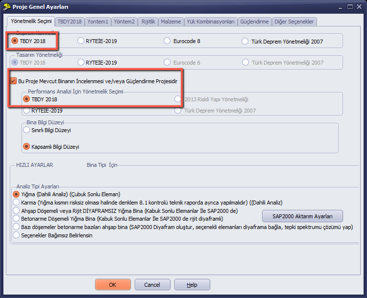
For StatiCAD to account for the retrofit in its calculations, the TBDY2018 code must be selected on the code selection page in the project general settings, and the option "This project is an Existing Building Assessment and Retrofit Project" must be checked. If the RYTEİE 2019 (Risky Building) code is selected, or if the option "This project is an Existing Building Assessment and Retrofit Project" is not checked, the retrofit will not be considered.
In Project General Settings > Retrofit Tab, options 1, 2, and 4 are selected.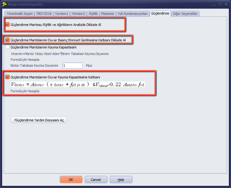
1. If Option 1 is not selected, the retrofit is not considered.
2. Option 2 enables the contribution of the retrofit to the compressive capacity to be taken into account. If the compressive strength of walls is sufficient, this option may be left unchecked.
3. Option 3 calculates the shear capacity increase from the wall retrofit assuming that only the shotcrete's shear strength is used and that the reinforcement is placed constructively. This is not recommended as it is overly conservative and uneconomical, but it may be applied at the engineer's discretion.
4. When Option 4 is selected, the shear strength of the shotcrete is not calculated; only the shear strength provided by the steel mesh reinforcement is considered. In our view, this is an economical and safe solution. In this option, the additional shear strength provided by the mesh reinforcement (to prevent brittle failure) is limited to 0.22*fcd*Amanto. If the shear strength of the retrofitted wall is still insufficient, increasing the shotcrete grade or jacket thickness as required by the formula may be a solution to achieve sufficient performance from the retrofit.
RETROFIT JACKET (SHOTCRETE) DRAWING
In order to calculate the composite (jacketed) capacities of walls in the retrofit, the retrofit jacket must be modeled on the static axis passing through the center of the wall. The start and end nodes of each wall segment and jacket segment must be the same. If this is applied, the jacket receives load from the slab in proportion to its stiffness, and the reinforcement is calculated by also taking the insufficient capacity portion of the wall as load.
If the start and end points of the wall are defined differently from the start and end points of the jacket, the jacket only receives load from the slab and reinforcement is calculated accordingly; it does not additionally receive load from the wall it is attached to. Reinforcement is calculated based on the load received from the slab.
The term "retrofit jacket" used in the program refers to a reinforced concrete layer formed by placing steel mesh on the wall applied with shotcrete or repair mortar and anchoring it to the wall, defining the retrofit.
To draw a retrofit jacket, press the  button on the main screen to bring up the Wall Retrofit Jacket Properties data entry form.
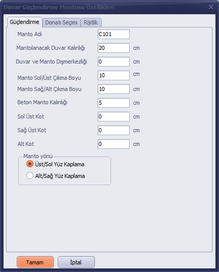
In the form that appears, the jacket name does not need to be changed as it is assigned automatically by the program. The thickness of the wall to be jacketed is entered in cm. The wall and jacket eccentricity value is kept at zero. The jacket left/bottom extension length determines how many cm the jacket will be extended to the left or bottom from the clicked point; the jacket right/top extension length determines how many cm it will be extended to the right or top. The concrete jacket thickness value is entered. If the building is not stepped or if the lower and upper level values of the walls are zero, the lower and upper levels of the concrete jacket should also be left at zero.
If the top or left face of the wall is to be coated, the Top/Left Face Coating radio button is selected; if the right or bottom face is to be coated, the Bottom Right Face radio button is selected.
When walls are jacketed from end to end, the program can calculate the required reinforcement for the jacket. If a specific value is desired, one of the available steel mesh options may be used.
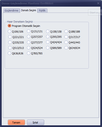
After clicking OK, the jacket is drawn by clicking the first and second points on the wall axis to be jacketed.
Drawing Retrofit Jackets
1-For the composite (jacketed) capacities of walls to be calculated in the retrofit, retrofit jackets and walls must be defined on the same axis.
2-There is no need to change the Jacket Name in the Wall Retrofit Jacket Properties. The program assigns element names automatically; if the names of elements drawn in a mixed order need to be sorted, automatic sorting can be done by pressing the Sort button on the upper toolbar.
3- The wall thickness value is entered in the jacketed wall thickness box.
4-For the jacket left/bottom extension length in exterior wall jackets, it may be appropriate to take half the thickness of the wall that is perpendicularly connected to the left or bottom of the wall to be jacketed. The left/bottom extension length determines how far ahead of or behind the left/bottom axis at which the jacket is defined the jacket will be drawn. Positive or negative values may be given.
6-For the jacket left/bottom extension length in interior wall jackets, it may be appropriate to take the negative value of half the thickness of the wall perpendicularly connected to the wall to be jacketed (e.g., -10). The left/bottom extension length determines how far ahead of or behind the left/bottom axis at which the jacket is defined the jacket will be drawn. Positive or negative values may be given.
7-For the definition of the jacket right/top extension length, refer to items (5) and (6).
8-The concrete jacket thickness must be at least 3 cm as required by the Earthquake Code. When static analysis is performed taking into account the stiffness of the jackets, the jacket thickness is one of the factors that determines the seismic load the jackets will carry.
9- Lower Level: if the storey you are modeling is a basement storey and your building is stepped, you may set the jacket lower level equal to the wall lower level.
10-Upper Level: if the storey you are modeling is the topmost storey and your building is stepped, you may set the jacket upper level equal to the wall upper level. If you enter the jacket lower or upper level differently from the wall lower or upper level, the analysis results may deviate from the expected results.
11- In a building application, providing the jacket lower or upper level differently from the wall lower or upper level may cause a reduction in the seismic performance of your building.
12-To cover the left face of vertical walls or the top face of horizontal walls, you may activate the top/left face coating option.
13-To cover the right face of vertical walls or the bottom face of horizontal walls, you may activate the bottom/right face coating option.
14- Click the OK Button and click on the axis intersection points on the main modeling screen to mark the first and second ends of the jacket. The jacket will be drawn.
15-If you wish to take into account the contribution of Retrofit Jackets to Wall Compressive Safety Stresses or to calculate the Contribution of Retrofit Jackets to Wall Shear Capacity, for exterior wall jackets you must set the start and end points of the jackets to be equal to or greater than the wall start or end points. (from the formula definition)
15-If you wish to take into account the contribution of Retrofit Jackets to Wall Compressive Safety Stresses or to calculate the Contribution of Retrofit Jackets to Wall Shear Capacity, for interior wall jackets you must set the start and end points of the jackets to be equal to or greater than the wall start or end points.
Since the jacket will be drawn at the intersection of the jacket and wall (the region where the jacket meets the perpendicularly connected wall) on screen and in drawings, there will be a surplus in jacket stiffnesses equal to the wall intersection area. However, this situation is taken into account in the analysis and the jacket areas are reduced by the area of the intersection region, so no discrepancy arises in calculations. In drawings, it would be appropriate to additionally trim (prune/delete) the jacket line at the wall-jacket intersection.
16-When a wall jacket is drawn to cover a door or window opening, the jackets are automatically divided by the door or window openings and constructive jackets are automatically created.
A Constructive Retrofit Jacket is the continuation of the jacket on the wall sections above and below windows or above doors. Continuing the jacket through wall openings increases the stiffness of the jackets on the solid wall sections and provides better retrofitting of the building. When drawing retrofit jackets, constructive jackets
are automatically created by the program at sections that coincide with doors or windows, and their properties can be changed by the user by modifying the information in this form.
Jacket Reinforcement
If a single type of reinforcement is to be used as jacket reinforcement throughout the building, first check "Let the program select automatically" in the reinforcement selection tab of the jacket properties window. After the analysis, to apply the maximum jacket reinforcement selected by the program to all jackets, select all jackets storey by storey (using the "Change properties of selected elements" option) and assign the maximum calculated steel mesh to all jackets in the reinforcement selection tab of the jacket properties window.
In calculation reports, the presence of a mesh grade larger than the Q785/785 steel mesh grade indicates that the required reinforcement area cannot be provided with standard steel mesh. For example, if Q1234/1234 mesh is calculated, this means 12.34 cm²/m of horizontal and vertical reinforcement must be used in that jacket.
In such a case, two Q634 reinforcements (2*634>1234) may be used within the jacket thickness,
or
for example, if single-row 12 mm diameter deformed bars are to be used: at spacing of 100/(12.34/(1.2*1.2*pi()/4)) = 9 cm,
or if double-row 12 mm diameter deformed bars are to be used: at spacing of 2*100/(12.34/(1.2*1.2*pi()/4)) = 18 cm reinforcement may be selected and drawings updated accordingly.
2-Strengthening Insufficient Walls by Adding Vertical Bond Beams
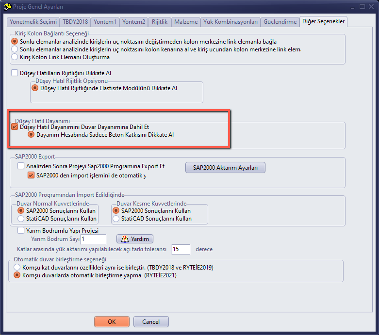
Checking the option shown in the image above causes the program to apply the following code clause.

After the "Include vertical bond beams in wall strength" option is checked, when vertical bond beams of sufficient cross-section are added inside the wall, insufficient walls may become sufficient.
3-Strengthening with Fiber-Reinforced Polymer (FRP) Wrapping
Select the insufficient walls, right-click on them, and click on "Change properties of selected wall."
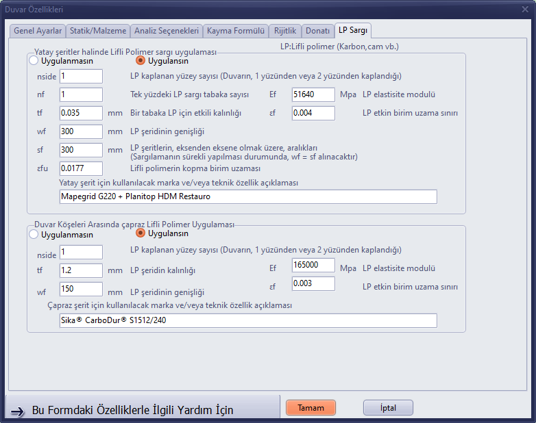
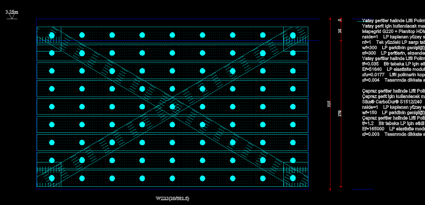
In the wall properties window, go to the FRP Wrapping Tab and select the option "Apply Horizontal Strip Fiber-Reinforced Polymer Wrapping" and/or "Apply Diagonal Fiber-Reinforced Polymer Wrapping Between Wall Corners."
Enter the values for the intended material in the input boxes and press OK.
After the analysis, check whether the wall has become sufficient. If it has not, repeat the analysis by changing the number of FRP wrapping layers on one face, the number of coated faces (whether the wall is coated on 1 or 2 faces), the spacing of FRP strips (center-to-center), the width of the FRP strip, or the material type/grade.
Static results can be checked from the wall shear stress report.
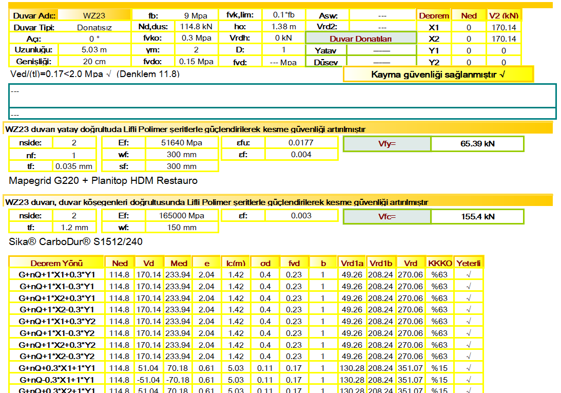
In the table above, the wall shear strength (Vrd) is found by adding the Vfy+Vfc values to the smaller of Vrd1a and Vrd1b for each loading case.
Vrd=min(Vrd1a,Vrd1b)+Vfy+Vfc
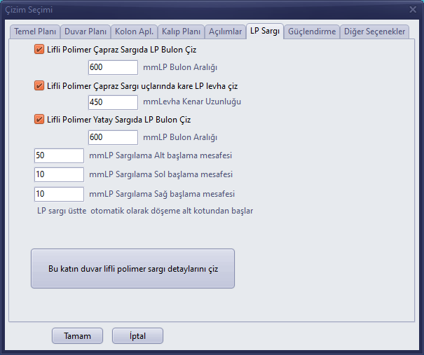
Drawings can be obtained from the drawing selection window.
Foundations
Since the code does not specify the effect of foundation deficiencies on the building in performance calculations, the program does not change the performance status of the building for foundation deficiencies. However, if there are deficiencies in the foundations (verified from foundation reports), analysis is performed with modified foundation cross-section dimensions until they become sufficient; retrofit drawings for the new sufficient foundation dimensions must be prepared separately by the user. For guidance on drawings, reference may be made to Prof. Zekai Celep's book "Introduction to Earthquake Engineering."