Worked Example: Braced Light Steel Panel
1. About this article
This article explains step by step how braced panel systems (TBDY 2018 10.4.2, 10.4.3) are defined in the StatiCAD light steel module, how the brace connection is checked, and how the design is improved by looking at the warnings. The starting model is the two-storey house described in detail in Worked Example: Two-Storey Light Steel Building; here some walls of that building are made strap-braced panels instead of sheathed panels. The project settings, floors, lintels and sheathed panels are as in the previous example; only the steps specific to the braced panel are described.
The inputs were entered from the interface (Wall Properties, multiple selection); all numbers in the article are the results the program gives in this example. All brace and connection checks of one wall (WZ12) are recalculated by hand in Section 8.
For the theoretical background and the details of the options, see the braced panel sections of the articles Light Steel Panel and Stud Design, Theoretical Basis of Light Steel Design and Light Steel Verification Studies.
You can download here the model files (ZIP): OrnekHafifCelikCapraz_ilk.sy4 (initial design) and OrnekHafifCelikCapraz.sy4 (final design).
2. Example building and braced walls
The building is 10 × 6 m, two storeys (storey height 2.80 m), with 24 light steel panel walls (C100×50×15 studs, 600 mm spacing, OSB on both faces). Earthquake: SS = 0.50, S1 = 0.14, ZC, equivalent seismic load method, R = 3, D = 2 (HCBTİE Table 1.2 limited ductility). The base shear is Vt = 70.0 kN in both directions and does not change when a braced panel is entered (the period is empirical).
Table 1 – Walls made braced (the other 18 walls remain sheathed)
| Storey | Wall | Direction | Wall length L | Location |
|---|---|---|---|---|
| Ground | WZ02 | X | 3.65 m | y = 0, x = 2.93–6.58 m (middle of the facade) |
| Ground | WZ05 | X | 3.65 m | y = 6 m, x = 2.93–6.58 m |
| Ground | WZ12 | Y | 4.15 m | x = 5 m interior wall |
| 1st storey | W102, W105, W112 | same | same | above those on the ground floor |
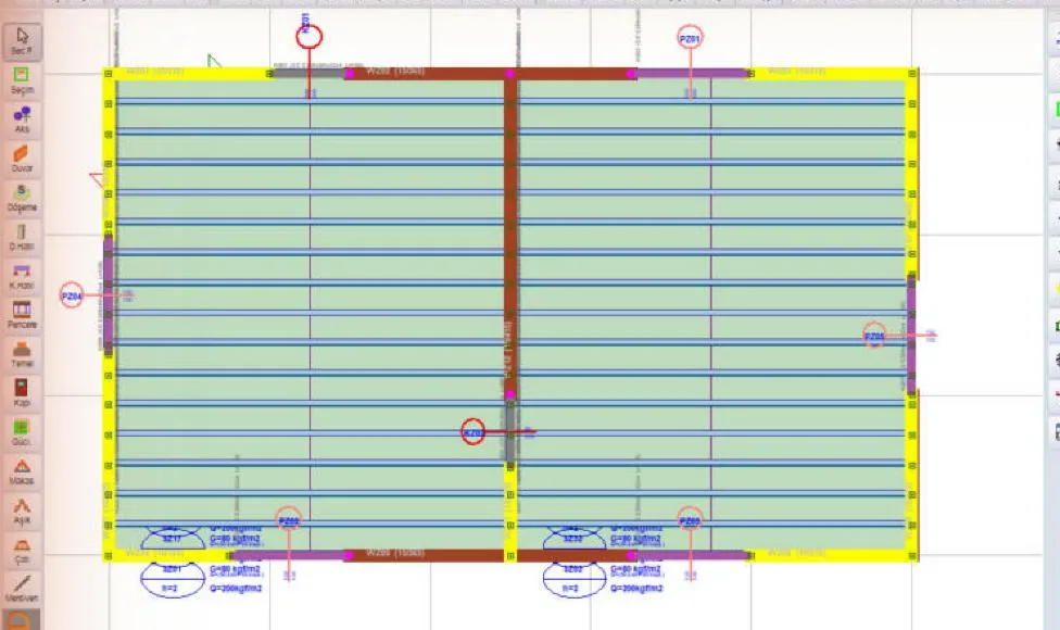
Figure 1 – Three walls selected in the ground floor plan (brown): WZ02, WZ05, WZ12
Mixed system and distribution of the seismic load: When sheathed and braced panels exist on the same storey, TBDY 10.2.6.1 requires the seismic load to be distributed according to the lateral load capacities of the panels. The program's default "Capacity" stiffness type does this: the FEM stiffness of each panel is made proportional to its capacity (Vc/0.6 for a braced panel, on the scale of Vn for a sheathed one). The comparison with the "Classical" type is in Section 9.
Ductility level: If there is a braced panel in the building, the structural system is considered Limited Ductility Level according to TBDY 10.2.1.2. In this example the project is already defined with limited ductility (R = 3, D = 2). If high ductility had been selected in the project settings, the analysis would give the line "Error: TBDY 10.2.1.2 (braced panel ductility)" and would check R and the height limits according to limited ductility.
3. Selecting the walls and the "Light Steel Brace" tab
- In the plan, click the first wall and add the others to the selection by clicking them with Shift held down (selected walls appear in brown).
- Right-click one of the selected walls and choose Change Properties of Selected Walls.
- On the Light Steel Brace tab, Panel system = Braced (TBDY 10.4.2). When Braced is selected, the shear capacity of the wall is calculated from the braces only; the sheathing continues only to restrain stud buckling.
- Brace type = Strap (tension only), strap width 100 mm, thickness 1.2 mm, material = stud material (S350GD), number of braced faces 2, number of bays 1.
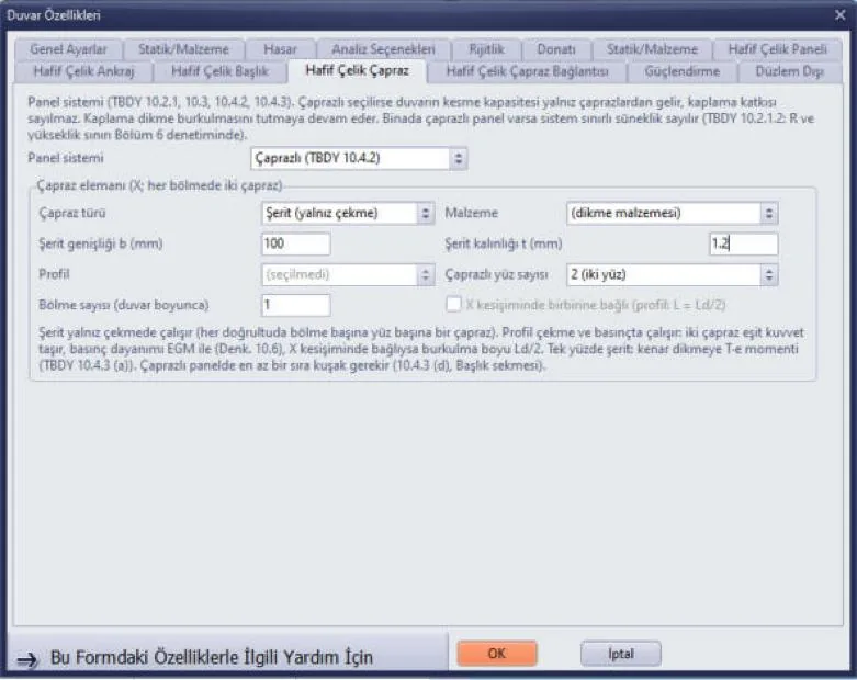
Figure 2 – The "Light Steel Brace" tab in multiple selection
Decimal separator: In these fields the decimal separator is the dot: type 1.2 (not 1,2).
Multiple selection: In multiple selection, the fields that differ among the selected walls come up blank (or with no selection in the drop-down list); only the specified fields are applied at OK.
4. Connection tab: initial inputs
In the top group of the Light Steel Brace Connection tab, only the basic inputs were given for the initial design: screw diameter 4.8 mm, screws per brace end 12, holes in the first row of the net section 2, gusset plate t = 0 (no plate: the strap is screwed directly to the stud and track). The "Pattern, gusset plate …" group below was left blank; the program builds a default pattern from the number of screws with the smallest permitted spacings (here 6 rows × 2 columns, p1 = p2 = e1 = 15 mm, e2 = 42.5 mm) and reports this with an information line.
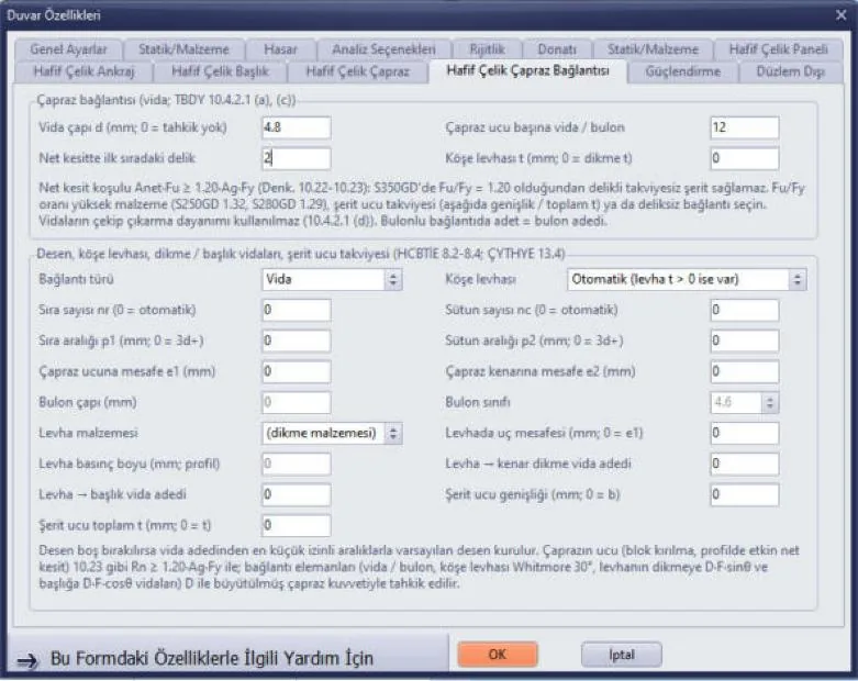
Figure 3 – Connection tab in the initial design
5. First analysis and warnings
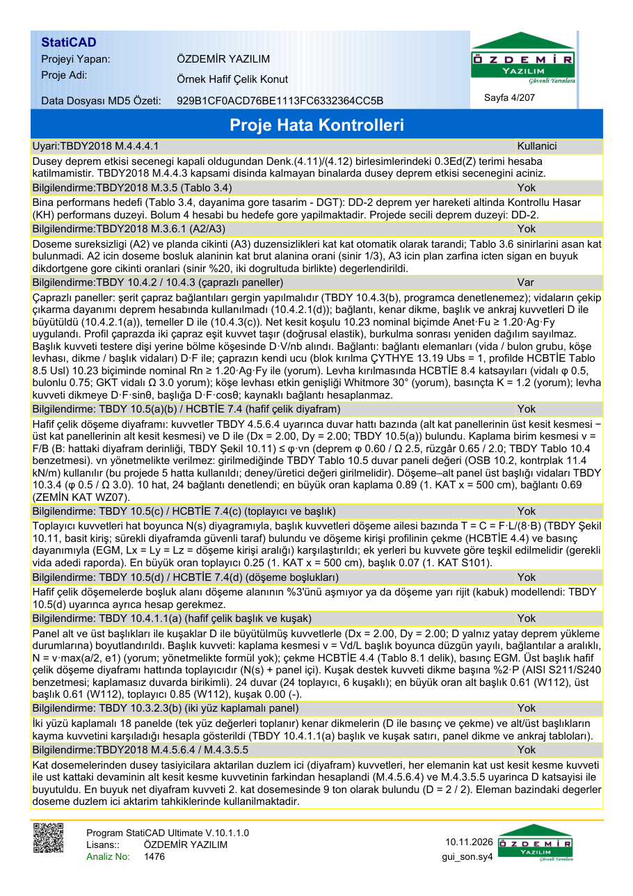
In the analysis window, Start Analysis. The initial design gave 51 lines; those related to the braced panel are grouped below (the numbers are for ground floor WZ02; similar in the other walls).
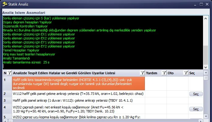
Figure 4 – Warning list of the first analysis (top)
Table 2 – Braced panel warnings of the initial design
| Warning | Value | Cause | Solution (Section 6) |
|---|---|---|---|
| Net section (TBDY Eq. 10.23) | AnetFu = 45.56 kN < 1.20·AgFy = 50.40 kN (0.90) | In S350GD, Fu/Fy = 1.20: a strap with holes ruptures before yielding | strap end reinforcement |
| Brace end rupture (block shear rupture) | Rn = 43.61 kN < 50.40 kN (1.16) | short and dense pattern (15 mm spacing) | long pattern, end reinforcement |
| Connection weaker than the brace | 12·Ps = 30.48 kN < Td = 37.80 kN | no plate: the screw goes into a 1.2 mm stud | gusset plate |
| No blocking (10.4.3(d)) | — | at least one row of blocking is mandatory in a braced panel | Track tab: 1 row |
| Bottom / top track inadequate | WZ12 bottom track N = 59.15 kN, ratio 1.48 (U100×53×1.5) | the horizontal component of the brace enters the track at the corner at a single point: N = D·V/nb | U100×54×2.5 track |
| W112 hold-down | ratio 1.02 (device 35 kN) | the braced wall attracts more shear | HD 45 kN |
| Roof diaphragm line x = 500 | v = 9.08 > 0.6·15 = 9.00 kN/m (1.01) | the force drawn by W112 comes from the diaphragm | vn 15 → 17 kN/m |
Why is the track so heavily loaded?: In a sheathed panel the shear force is transferred to the track as uniformly distributed along its length (sawtooth model); in a braced panel the force of the brace enters the track at a single point at the bay corner and is carried from there to the shear anchors. For this reason the track of a braced panel carries a larger axial force (TBDY 10.4.2.1(a): tracks with the brace force magnified by D).
6. Improving the design
The three walls were selected again and the following were entered in the multiple-property form (the same values for the three walls on the 1st storey as well):
Table 3 – Improvement steps
| Step | Tab / field | Value | Effect |
|---|---|---|---|
| 1. Strap end reinforcement | Connection: strap end total t | 2.4 mm (double-layer strap in the connection zone) | net section 0.90 → 1.81 (Anet = (100 − 2·4.8)·2.4 = 216.96 mm²) |
| 2. Long pattern | Connection: nr × nc, p1, p2, e1 | 6 × 2, 20 / 40 / 30 mm | block shear rupture Rn 43.6 → 160.8 kN (ratio 0.31) |
| 3. Gusset plate | Connection: gusset plate = Yes, t | 2 mm (stud material S350GD) | screw Ps 2.54 → 5.44 kN, fastener group 65.3 kN ≥ Td 37.8 kN (ductile) |
| 4. Plate screws | Connection: plate → chord stud / track | 8 / 6 screws (the program gave the required number as 6 / 4 and 6 / 6) | C1 ≤ 0.74, C2 ≤ 0.92 |
| 5. Blocking and track | Track: blocking row, bottom / top track | 1 row; U100×54×2.5 | blocking and track errors disappear |
| 6. Anchor, diaphragm | Anchor (W112); roof floor Light Steel tab | HD = 45 kN, storey connection 45 kN; vn = 17 kN/m | anchor 1.02 → < 1, diaphragm 1.01 → 0.89 |
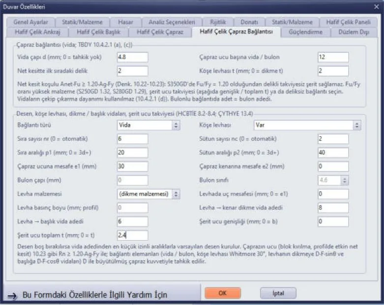
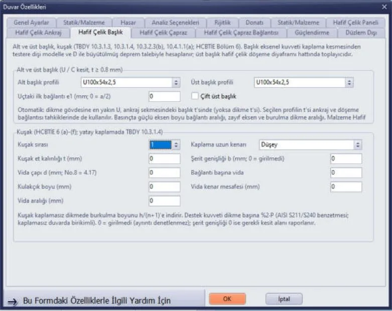
Pattern first, then plate: In a screwed thin strap, two limit states almost always govern: the net section (10.23) and block shear rupture at the brace end. Both are rupture of the brace's own end and are checked not with D but in the form of 10.23 with Rn ≥ 1.20·AgFy: the brace must not rupture at its end before it yields. End reinforcement and a pattern with few columns, many rows and a large e1 solve both together. The connection elements (screw group, gusset plate, plate screws), on the other hand, are checked with the brace force magnified by D.
Applying the end reinforcement: The "Strap end total t" input assumes that the thickness of the strap is increased in the connection zone (e.g. a second layer of the same strap). The reinforcement must be long enough to cover all screws of the connection and the two layers must be connected to each other; the screw is assumed to pass through both layers (t1 = 2.4 mm).
7. Final analysis and results
In the second analysis no error lines remained; the list consists only of information lines (the orange wind line is a notice also present in the previous example: no wind load is defined in the model).
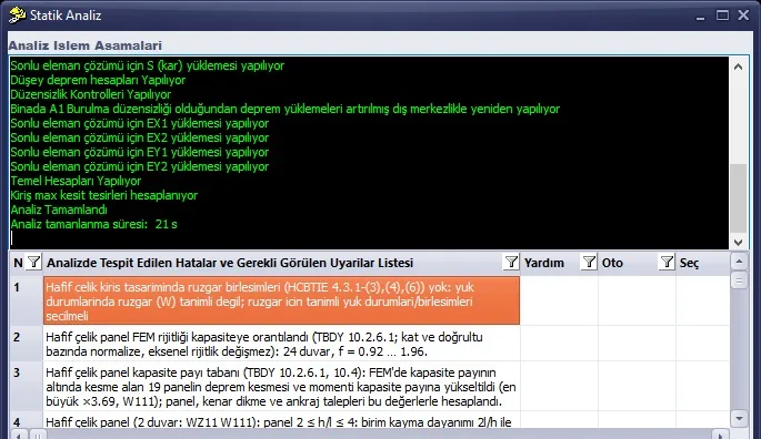
Figure 7 – Warning list of the final analysis (top)
Table 4 – Final results of the braced walls (YDKT)
| Wall | θ | V (kN) | D | F (kN) | F/Td | Net section | Connection ratio (governing) | Ductile |
|---|---|---|---|---|---|---|---|---|
| WZ02 | 35.5° | 20.86 | 1.98 | 12.81 | 0.34 | 1.81 | 0.73 (C1 stud screws) | yes |
| WZ05 | 35.5° | 21.22 | 1.98 | 13.03 | 0.34 | 1.81 | 0.74 (C1) | yes |
| WZ12 | 32.1° | 32.18 | 1.84 | 18.99 | 0.50 | 1.81 | 0.91 (C2 track screws) | yes |
| W102 | 35.5° | 13.72 | 1.98 | 8.42 | 0.22 | 1.81 | 0.48 (C1) | yes |
| W105 | 35.5° | 13.89 | 1.95 | 8.53 | 0.23 | 1.81 | 0.48 (C1) | yes |
| W112 | 32.1° | 37.12 | 1.63 | 21.90 | 0.58 | 1.81 | 0.92 (C2) | yes |
V: seismic shear of the wall without D; D = Vd/V (on the basis of the capacity share and with D by storey); F = V/(nb·ny·cos θ); Td = 0.90·AgFy = 37.80 kN. Panel shear capacity Vc = 2·37.80·cos θ = 61.58 kN (L = 3.65 m) / 64.07 kN (L = 4.15 m). θ = atan(h/L), h = stud length 2.60 m.
8. Verification by hand for WZ12
WZ12: L = 4.15 m, h = 2.60 m (panel height = stud length: storey height 2.80 m − bond beam above the wall 0.20 m; the brace is the diagonal of the frame between the bottom and top track), single bay, strap 100×1.2 mm S350GD on two faces (Fy = 350, Fu = 420 MPa), end reinforcement tend = 2.4 mm, gusset plate 2 mm S350GD, screw 4.8 mm, pattern 6×2 (p1 = 20, p2 = 40, e1 = 30, e2 = (100 − 40)/2 = 30 mm), stud t = 1.5 mm, track t = 2.5 mm.
Table 5 – WZ12 hand calculation (the program gives the same values)
| Quantity | Calculation | Result |
|---|---|---|
| Angle | θ = atan(2.60/4.15) | 32.07°, cos θ = 0.84742, sin θ = 0.53092 |
| Brace capacity (10.21b) | Td = 0.90·120·350 | 37.80 kN |
| Panel capacity | Vc = 1·2·37.80·0.84742 | 64.07 kN |
| Brace force | F = 32.18/(2·0.84742) | 18.99 kN → F/Td = 0.50 |
| Connection demand (10.4.2.1(a)) | D·F = 1.838·18.99 | 34.90 kN |
| Net section (10.23, with end reinforcement) | AnetFu = (100 − 2·4.8)·2.4·420 = 91.12 kN ≥ 1.20·120·350 = 50.40 kN | ratio 1.81 (satisfied) |
| A1 screw group | t2/t1 = 2.0/2.4 < 1: Pns = min(4.2√(2³·4.8)·420; 2.7·2.4·4.8·420; 2.7·2.0·4.8·420) = min(10932; 13064; 10886) = 10886 N; Ps = 0.5·10886 = 5443 N; 12·5.443 | 65.32 kN → 34.90/65.32 = 0.53 |
| A4 block shear rupture, brace end (ÇYTHYE 13.19) | Lgv = 30 + 5·20 = 130 mm; Agv = 2·130·2.4 = 624; Anv = 2·(130 − 5.5·4.8)·2.4 = 497.28; Ant = (40 − 4.8)·2.4 = 84.48 mm² (tear-out to the edge 2·(30 − 2.4)·2.4 = 132.48, larger); Rn = min(0.6·420·497.28 + 420·84.48; 0.6·350·624 + 420·84.48) = min(160.80; 166.52) | Rn = 160.80 kN ≥ 50.40 kN → 0.31 |
| B2 gusset plate Whitmore | lw = 40 + 2·100·tan30° = 155.47 mm; yielding 0.9·350·155.47·2 = 97.95 kN; rupture 0.5·420·(155.47 − 2·4.8)·2 = 61.27 kN | 0.36 / 0.57 |
| B3 block shear rupture, plate | same surfaces t = 2: Rn = min(0.6·420·414.4 + 420·70.4; 0.6·350·520 + 420·70.4) = 134.00 kN; φ = 0.5 | 67.00 kN → 0.52 |
| C1 plate → stud | D·F·sin θ = 18.53 kN; Pns(t1 = 2, t2 = 1.5) = min(4.2√(1.5³·4.8)·420; 10886; 8165) = 7100 N, Ps = 3550 N; 8 screws = 28.40 kN | 0.65 |
| C2 plate → track | D·F·cos θ = 29.57 kN; t2/t1 = 1.25 (interpolation) Pns = 10886 N, Ps = 5443 N; 6 screws = 32.66 kN | 0.91 (governing) |
| Ductility | weakest connection element min(65.32; 97.95; 61.27; 67.00) = 61.27 kN ≥ Td = 37.80 kN | ductile |
Factors: For rupture and block shear rupture of thin sheet (t < 4 mm), the HCBTİE 8.4 factors: screwed φ = 0.5, bolted 0.75. For screw shear, TBDY 10.12 φ = 0.5. The Whitmore width (30° spread) is interpretation; ÇYTHYE 13.4.1 says "taking the stress distribution in the plate into account appropriately".
9. Stiffness type: "Capacity" and "Classical"
When the light steel panel stiffness type in Project General Settings is selected as "Classical" and the same model is solved, the braces enter the finite element model as explicit diagonal bars (two diagonals in each wall, Am = (k/2)·Lm/(E cos²θm); in WZ12 the target lateral stiffness k = 7144 kN/m, diagonal area 128.0 mm²) and the shear share of the walls is distributed according to the elastic stiffnesses.
Table 6 – Seismic shear of braced walls without D by stiffness type
| Wall | Capacity (V, kN) | Classical (V, kN) |
|---|---|---|
| WZ02 | 20.86 | 19.17 |
| WZ12 | 32.18 | 23.84 |
| W102 | 13.72 | 12.53 |
| W112 | 37.12 | 17.19 |
In the Classical type, braced walls receive less shear; the shear shifts to the elastically stiffer sheathed panels, and in this model the hold-downs of 15 walls (13 of them sheathed) become inadequate. Since TBDY 10.2.6.1 requires the distribution in a mixed system to be made according to the panel capacities, the default "Capacity" type is recommended; the "Classical" type is for comparison and for the drift check.
10. Calculation report
In the "Light Steel Stud Design (EGM)" report in Report Selection, the panel shear row of each braced wall gives, under the heading BRACED PANEL, the brace, net section, connection pattern, gusset plate, the capacity / ratio of each connection link and the ductile behaviour status. On the Project Error Checks page, the assumptions of braced panels appear as an information line.
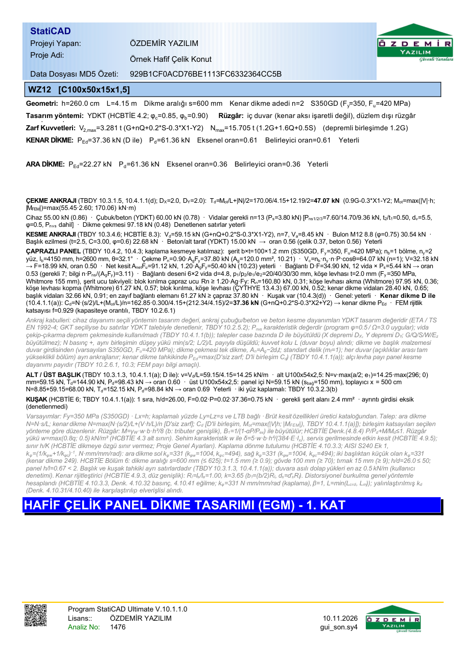
11. Plan and elevation drawing
In Drawing Selection, the wall plan and Elevations → Draw Section / Side View (axis elevations) show braced walls separately. The drawings use the analysis result: the analysis must be run first. The figures were taken from the drawing window of the program for the final design (and for the initial design for comparison).
11.1 Wall plan
In a braced wall, on each braced face there is a green brace line 1 cm outside the stud flange (two lines in a two-face panel) and an X symbol across the wall thickness in the middle of each bay. The brace label (number of faces, strap b×t, material, number of bays, end reinforcement) is at the upper side of the wall, above the stud and shear anchor labels. The explanation line below the sheet defines the symbols.
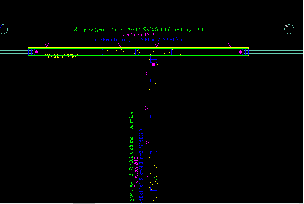
Figure 10 – Ground floor wall plan: junction of WZ02 and WZ12 (green face lines, X symbol, brace label)
11.2 Axis elevation
In the elevation, two braces are drawn in each bay from the panel corner to the opposite corner, as a band of the strap width. If a gusset plate is defined, a right-triangle plate at the four corners, an nr × nc screw pattern (p1, p2, e1) at the brace ends and the screws connecting the plate to the chord stud and the track are visible. The text block is in the upper triangle between the two braces, away from the crossing of the X, below the dimension chain: first the brace and end connection lines, then the stud, track and anchor lines.
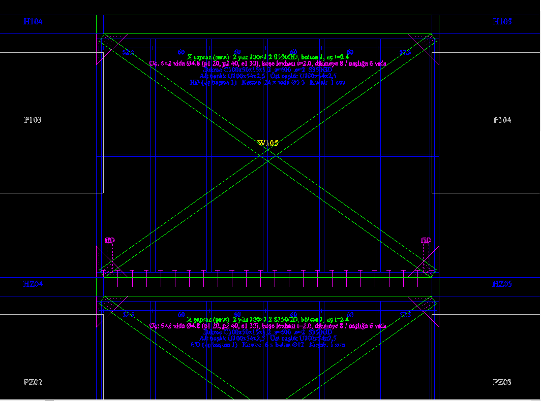
Figure 11 – Final design, W105 (1st storey) and WZ05 below it: X braces, gusset plates, text block
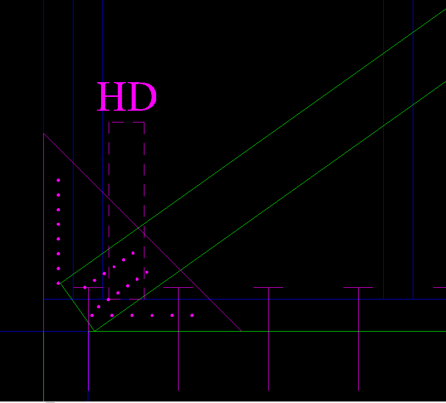
Figure 12 – W105 bottom left corner: 2 mm gusset plate, 6×2 screw pattern, 8 screws to the stud and 6 to the track in the plate; HD behind the plate (dashed)
HD and gusset plate: The hold-down (HD) is connected to the chord stud; since it overlaps the gusset plate, the part left behind the plate is drawn with a dashed line, and the label “HD” is above the plate. The plate size and the layout of the pattern are a drawing assumption (the plate leg includes the pattern and the plate end distance, and is not larger than 45% of the bay); the responsible engineer determines the construction detail.
11.3 Elevation of an inadequate design
If, in the last analysis, the brace force / net section condition or a link of the connection is inadequate, or the connection is weaker than the brace, the relevant brace, pattern and text lines are drawn on the HafifCelikYetersiz (red) layer. In the initial design (no plate, 6×2 pattern, p = e1 = 15 mm; net section and block shear rupture inadequate, Section 5) the braces and the connection are red; the bottom and top tracks are also red (corner force D·V/nb).
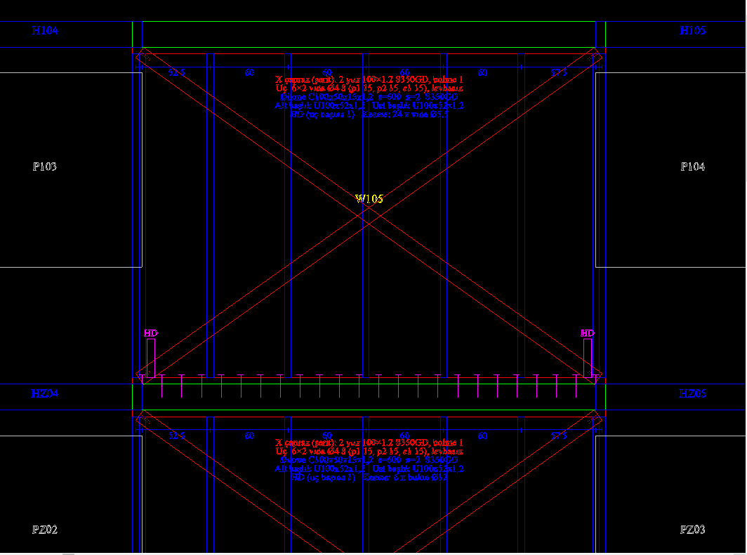
Figure 13 – Initial design, W105: inadequate brace, connection and tracks in the red layer
Table 7 – Drawing layers
| Layer | Colour | Content |
|---|---|---|
| HafifCelikCapraz | green | brace band, face line and X in the plan, brace label |
| HafifCelikBaglanti | magenta | gusset plate, end pattern, plate screws, HD, shear anchors, connection label |
| HafifCelikDikme | blue | studs, tracks, blocking, dimension chain |
| HafifCelikYetersiz | red | items found inadequate in the last analysis |
12. Points to note and known limits
- Panel height: in the brace geometry h = stud length (storey height − height of the bond beam above the wall; in this example 2.80 − 0.20 = 2.60 m) is taken; it is the same as the frame height drawn in the axis elevation. The h/l condition of sheathed panels is checked with the storey height.
- Taut connection (TBDY 10.4.3(b)) and strap pretensioning cannot be checked by the program; they must be ensured in the site detail.
- A welded connection is not calculated (HCBTİE Section 8 covers screwed / bolted connections).
- Gusset plate compression (ÇYTHYE 13.4.4) is checked only for a profile brace; if the free compression length of the plate is not entered, 50 mm is taken.
- The bottom and top corners are assumed to have the same detail. The plate force is resolved into D·F·sin θ on the stud and D·F·cos θ on the track (work point at the corner).
- If a strap is used on one face, the eccentricity moment T·e is added to the chord stud (TBDY 10.4.3(a)); in this example two faces were used.
- If the blocking detail inputs (blocking t, screw) are not entered, the blocking connection is not checked; an information line is given.