Worked Example: Two-Storey Cold-Formed Steel Building
1. About this article
This article shows, with screenshots, how a small two-storey house is modelled and solved from start to finish with the cold-formed (light-gauge) steel module (LSF) of StatiCAD: project settings, panel walls, door/window headers, cold-formed steel floor (strip + floor joist generation), analysis, reading the warnings and refining the design, results, calculation report and drawings. The values entered at each step are the actual values of the example building; the numerical results in the article are the results the program gives for this example.
For the theoretical background of the modules and the details of all options, see these articles: Cold-Formed Steel Panel and Stud Design, Cold-Formed Steel Beam and Column Design, Cold-Formed Steel Floor: Floor Joists and Diaphragm, Code Requirements, Anchors and Foundation, Theoretical Basis and Verification Studies.
Edition: The Cold-Formed Steel building type, the “Panel in Cold-Formed Steel” wall type, the cold-formed steel beam/floor tabs and the cold-formed steel reports appear only in the StatiCAD Ultimate edition. The screenshots were taken with StatiCAD Ultimate V.10.0.1.0.
Example files: You can download the project files of the two stages in the article (ZIP): OrnekHafifCelik_ilk.sy4 (initial design, Chapter 9) and OrnekHafifCelik.sy4 (refined design, Chapters 10–13). Open the file with File › Open and follow the steps on your own screen.
2. Example building
A detached two-storey house with a plan of 10.00 × 6.00 m. The structural system is entirely cold-formed steel: panel walls with a storey height of 2.80 m, C200 floor joists bearing on the panels, and cold-formed steel headers above doors/windows. The foundation is outside the scope of this example; the wall bases are assumed to be supported.
Table 1 – General information
| Item | Value |
|---|---|
| Plan | 10.00 × 6.00 m (x = 0…10 m, y = 0…6 m); interior bearing wall at x = 5.00 m |
| Storeys | ZEMİN KAT (ground floor) and 1. KAT (1st floor), 2.80 m each (building height 5.60 m) |
| Walls (panels) | Thickness 15 cm; stud C100x50x15x1.2 (exterior wall), C100x50x15x1.5 (interior wall), spacing 600 mm, 2 edge studs at panel end; 11 mm OSB on both faces (vc = 10.2 kN/m); wall unit weight 300 kg/m³ |
| Openings | Ground floor: 2 doors (1.00 m entrance, 0.90 m interior door) and 5 windows; 1st floor: 1 interior door and 6 windows (windows 1.50 m, sill 90 cm) |
| Headers | Cold-formed steel beam CC C200x80x22x4 above each opening, hinged at both ends |
| Slabs | Two 5.00 × 6.00 m slabs on each floor; cold-formed steel floor: CC C200x80x16x2 floor joists in the X direction, spacing ≤ 390 mm (generated 375 mm), OSB sheathing, two rows of bridging |
| Loads | Slab thickness 2 cm (sheathing + screed equivalent), additional dead load 30 kg/m², live load 200 kg/m² (ground floor), 150 kg/m² (roof); snow load on roof Sk = 0.75 kN/m²; wind q = 0.5 kN/m² (TS 498, 0–8 m) |
| Earthquake | TBDY 2018, DD-2, SS = 0.50, S1 = 0.14, ZC; I = 1, R = 3, D = 2 (HCBTİE Table 1.2, limited ductility); Equivalent Seismic Load Method, T = 0.2 s (TBDY 10.2.6.1) |
| Design method | LRFD (HCBTİE 4.2; φc = 0.85, φb = 0.90) |
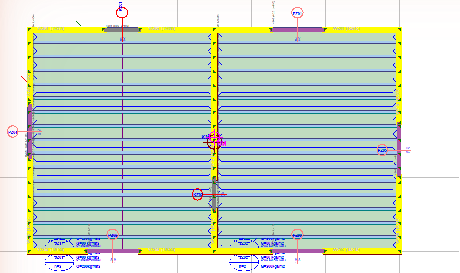
Figure 1 – Ground floor plan: panel walls (yellow), floor joists (blue), strips (green), doors and windows (purple)
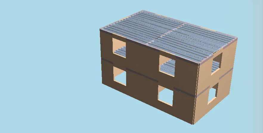
Figure 2 – 3D view of the example building
Plan orientation: In the StatiCAD plan screen the y axis points downwards: the façade at y = 0 appears at the top of the screen, the façade at y = 600 cm at the bottom.
3. Starting the program and the project
When the program opens, the start (dock) screen appears. Use New on the left for a new project and Open for a ready-made example; the Main Screen icon opens the working screen.

Figure 3 – Start (dock) screen
The main screen has the plan (storey) view on the left and the 3D view on the right. In the top toolbar, PrjAyar (Project Settings) opens the Project General Settings, KatAyar (Storey Settings) the General Storey Settings, Analiz (Analysis) the Static Analysis window, Rapor (Report) the Report Selection and Çizim (Drawing) the Drawing Selection. The Lower Storey / Upper Storey buttons change the active storey (“Active Story” at the bottom left).
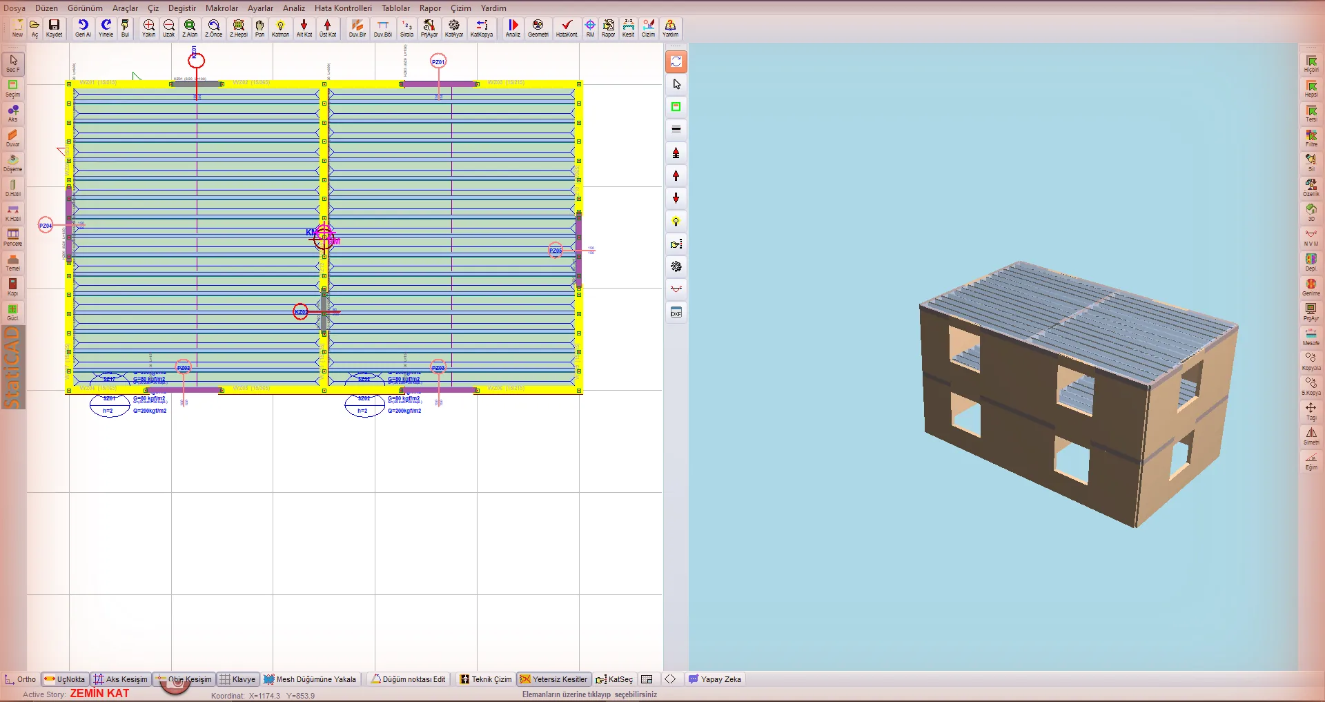
Figure 4 – Main working screen: ground floor plan and 3D view
4. Project General Settings
Opened with PrjAyar in the top toolbar. The tabs required for a cold-formed steel building are below.
4.1 Code Selection: building type and cold-formed steel options
- Building Type: Cold-Formed Steel is selected. This selection activates the use of T = 0.2 s in the seismic calculation, the cold-formed steel project checks (HCBTİE Table 1.2) and the cold-formed steel tabs.
- Seismic Forces: TBDY 2018, Ductility Level: Limited (R ≤ 3). With high ductility R ≤ 4 can be used.
- Cold-Formed Steel Member Design Method: LRFD. Stud deflection limit h/240 (gypsum/OSB sheathing), distortional buckling finite strip for C+ (default).
- Load Distribution to Shear Walls in Timber and Cold-Formed Steel Buildings: Capacity. The seismic load is distributed to the panels in proportion to their capacities (TBDY 10.2.6.1).
- “Take eccentricities into account in the system stiffness matrix (offset3)” and “Take Offset1 and Offset2 values into account in the system stiffness matrix” boxes are left unticked in this example; leaving them ticked does not change the cold-formed steel beam design (see the note below).
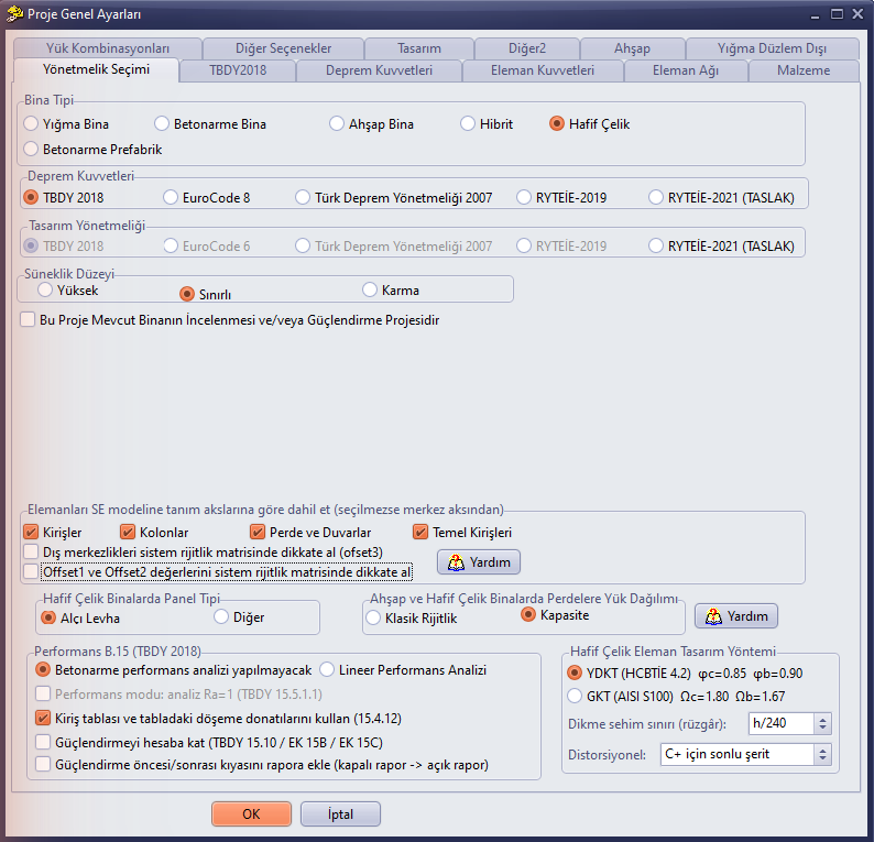
Figure 5 – Project General Settings › Code Selection (Cold-Formed Steel building type, LRFD, capacity distribution, offset boxes off)
Offset boxes and floor joists: If either offset box is ticked, the beam axis is modelled below the floor plane; together with the rigid diaphragm constraint, an axial force (composite effect) with no real load path arises in the joist. In this example the FEM gives about 29 kN of this force per floor joist. In cold-formed steel beam design, as for reinforced concrete beams, the program subtracts this share from the axial force: with the boxes ticked the design axial force is 0.2 kN and P/Pd + M/Md = 0.564; with the boxes off, 0 and 0.558. The raw axial force continues to appear in the FEM beam result tables. The “Offset1 and Offset2” box is not saved in the project file and the program opens it ticked every time.
Panel Type selection: The “Panel Type in Cold-Formed Steel Buildings (Gypsum Board / Other)” selection on the same tab has no effect on the calculations in this edition. The sheathing type and strength are entered for each wall in the Cold-Formed Steel Panel tab (Chapter 6.4).
4.2 TBDY2018: seismic parameters
The DD-2 map spectral acceleration coefficients (SS = 0.50, S1 = 0.14), local soil class ZC, building importance factor I = 1, response modification coefficients R(x) = R(y) = 3 and overstrength factors D(X) = D(Y) = 2 are entered. HCBTİE Table 1.2 requires D = 2 for cold-formed steel buildings; R cannot exceed 3 for limited ductility.
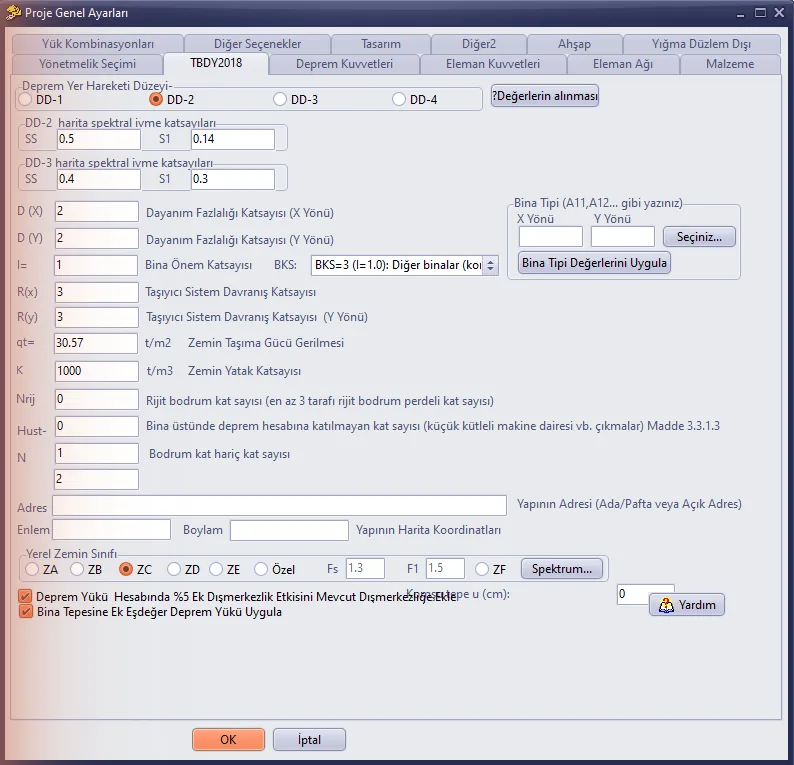
Figure 6 – Project General Settings › TBDY2018
4.3 Seismic Forces
Equivalent Seismic Load is selected (TBDY 10.2.6.1). When the building type is Cold-Formed Steel, the program sets the period option to Empirical Method; in a cold-formed steel building the spectral acceleration is always calculated with T = 0.2 s, so the period selection does not change the result.
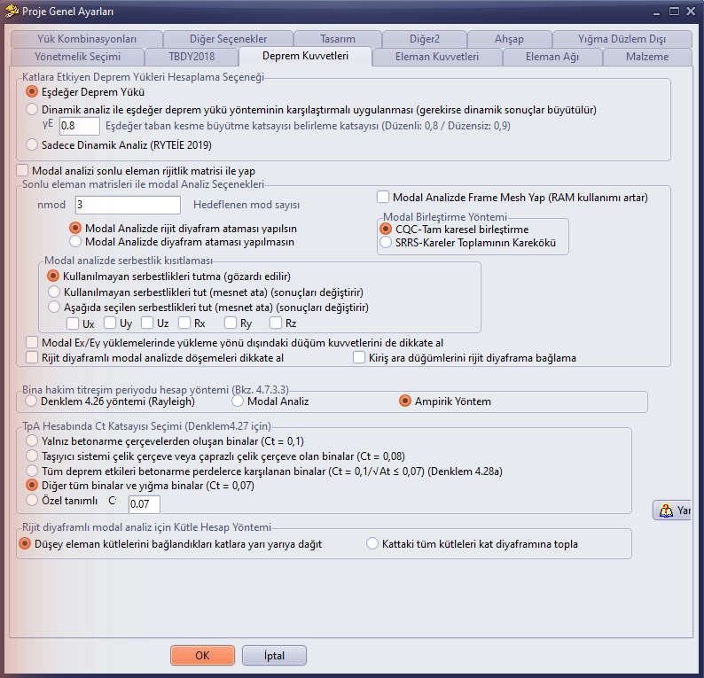
Figure 7 – Project General Settings › Seismic Forces
4.4 Load Combinations: wind and snow
The wind pressure q of 0.5 kN/m² (TS 498, 0–8 m) and the roof snow load Sk of 0.75 kN/m² are entered. q is used in the out-of-plane wind check of the exterior wall studs (1.2G + 1.0Q + 0.5S + 1.6W) and in the stud deflection; the snow load acts on slabs marked “Snow Load: Yes” (in this example the roof).
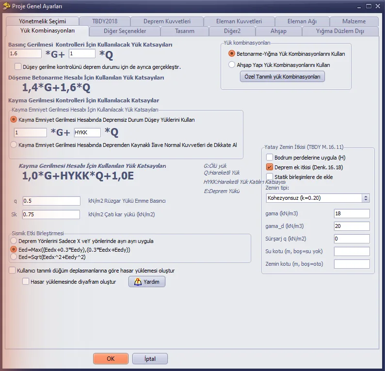
Figure 8 – Project General Settings › Load Combinations
Wind load case: While “Use Reinforced Concrete–Masonry Load Combinations” is selected, there is no wind among the load cases. The wind check of the studs is made independently of this; in cold-formed steel beam/column design, however, no wind combinations arise and an information line appears at the end of the analysis (Chapter 10.4).
4.5 Member Forces: load transfer and diaphragm
For load transfer from slabs, Classical Method is selected and Include Slabs in System Stiffness is left unticked; thus each floor joist receives the G and Q of its own load width. Fully rigid diaphragm is used for the seismic loadings.
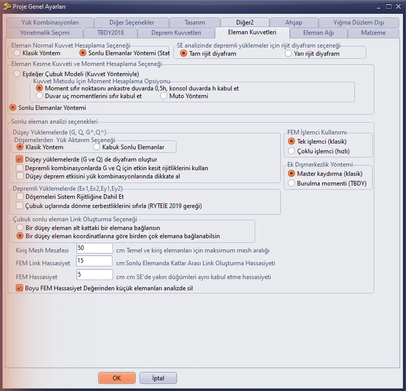
Figure 9 – Project General Settings › Member Forces
5. Storey definitions
In the KatAyar (General Storey Settings) window two storeys are defined: ZEMİN KAT and 1. KAT, 280 cm each. The TEMEL row is the foundation storey of the program; no foundation member is drawn in this example.
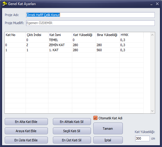
Figure 10 – General Storey Settings
6. Cold-formed steel panels (walls)
6.1 Drawing the walls
Walls are drawn with two clicks along a grid line using the Wall button on the left bar (or w on the command line); the wall thickness is 15 cm. In StatiCAD each wall is a full-height panel segment: the wall ends at door and window openings (Chapter 7). There are 12 panels on each of the ground floor and the 1st floor (WZ01…WZ12, W101…W112).
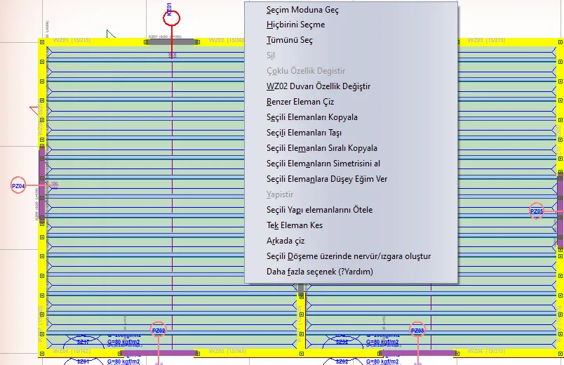
Figure 11 – Right click on a wall: "WZ02 Duvarı Özellik Değiştir" (Change Properties of Wall WZ02)
To change the properties, right-click the wall and select … Duvarı Özellik Değiştir (Change Wall Properties); when several walls are selected, Çoklu Özellik Değiştir (Change Multiple Properties) applies the same values to all selected walls.
6.2 General Settings: “Panel in Cold-Formed Steel”
- Member Type: Panel in Cold-Formed Steel is ticked. The “Cold-Formed Steel Panel” and “Cold-Formed Steel Anchor” tabs become visible with this selection.
- Wall Width 15 cm, Left/Right Delta 7.5 cm (wall centred on the grid line).
- Bond Beam Height 20 cm is entered. In a cold-formed steel panel this value is the floor depth: the stud height is taken as h = 280 − 20 = 260 cm (in the report “Geometri: h = 260 cm”, i.e. Geometry).
- The building edge where the wall is located is ticked in the Shear Wall Position boxes (for this wall On Bottom Edge Axis). Wind bending and stud deflection are calculated only for walls whose edge axis is ticked (exterior walls); the boxes are left empty for an interior wall.
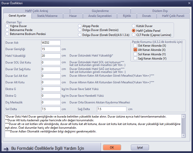
Figure 12 – Wall Properties › General Settings (Panel in Cold-Formed Steel, On Bottom Edge Axis)
6.3 Static/Material: wall weight
The self-weight of the panel is calculated from the BHA (unit weight) on this tab and the wall thickness. In the example 300 kg/m³ × 0.15 m ≈ 45 kg/m² of wall surface is taken (stud, two layers of OSB, insulation and interior gypsum board). Masonry strength fields such as fk and fvko are not used in the cold-formed steel panel calculation.
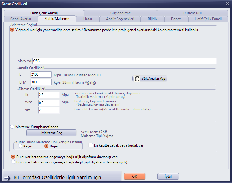
Figure 13 – Wall Properties › Static/Material (BHA = 300 kg/m³)
Default wall weight: Newly drawn walls come with the masonry wall defaults (1300 kg/m³, 24 cm). When “Panel in Cold-Formed Steel” is selected, the thickness becomes 15 cm and BHA 300 kg/m³; the Left/Right Delta (end extensions) scales in proportion to the thickness (12 → 7.5 cm). When a saved cold-formed steel wall is opened, the saved values are kept. If the actual thickness and weight of the panel are different, correct these values; if the masonry values (1300 kg/m³ × 0.24 m ≈ 3 kN/m²) remain, the seismic mass and stud loads are calculated several times too large.
6.4 Cold-Formed Steel Panel tab
- Left/Top and Right/Bottom Panel Sheathing Present are ticked; for 11 mm OSB on both faces vc = 10.2 kN/m (TBDY Table 10.5; screw spacing 150 mm at the edge, 300 mm in the field). Design value of the panel shear strength φ·Vn = 0.6 · vc · L (for each face; two faces with equal sheathing are added).
- Stud Section C100x50x15x1.2 (exterior walls) / C100x50x15x1.5 (interior wall), Stud spacing 600 mm, Number of edge studs 2.
- Rotational restraint of the sheathing on the stud kφ: two faces of OSB, EIw 0 (the default of the type), screw spacing 300 mm. The program uses the smaller of the two faces; with OSB the distortional strength of the stud increases (in the example kφ = 233 N·mm/mm/rad).
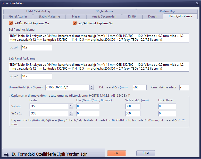
Figure 14 – Wall Properties › Cold-Formed Steel Panel
Choice of sheathing: If the panel shear strength is insufficient, first strengthen the sheathing (OSB, plywood or sheet steel on both faces), then increase the panel length. Gypsum board alone cannot carry the seismic load (TBDY 10.2.7.2); the contribution of gypsum-board panels to the seismic strength of the storey is reported.
6.5 Cold-Formed Steel Anchor tab
The tension anchor (hold-down) at each end of the panel and the shear anchor along the base are defined here. The values are the design strengths of the selected method (LRFD) (manufacturer/ETA). On the ground floor the shear anchor is entered as a bolt into the foundation concrete (M12, 8.8, spacing 600 mm), on the 1st floor as a screw into the floor slab (5.5 mm, spacing 150 mm).
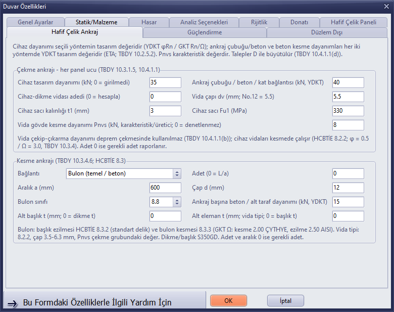
Figure 15 – Cold-Formed Steel Anchor – initial design: device 35 kN, anchor rod/concrete 40 kN
Meaning of the values: Device design strength: the φRn value of the hold-down device; Anchor rod/concrete/storey connection: the strength of the rod and concrete cone connecting the device to the foundation or lower storey. If Device-stud screw count = 0 is entered, the program calculates and reports the required number of screws. Pnvs: shear strength of the screw shank (manufacturer, characteristic).
7. Doors, windows and headers
The Door and Window buttons on the left bar open tool windows: the distance, width and height (sill height for a window) are entered; one clicks an end of the wall (reference) and then a point on the same wall in the direction of the opening. The program splits the wall at the edges of the opening; the walls on either side of the opening are separate panels.
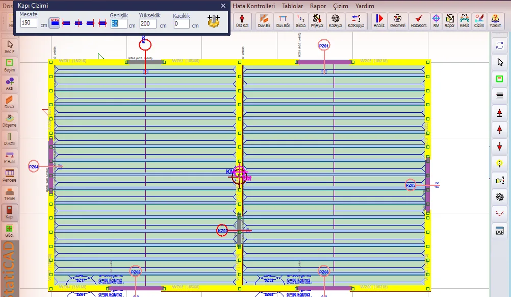
Figure 16 – Door Drawing tool window (distance 150 cm, width 90 cm, height 200 cm)

Figure 17 – Status bar hint in door mode
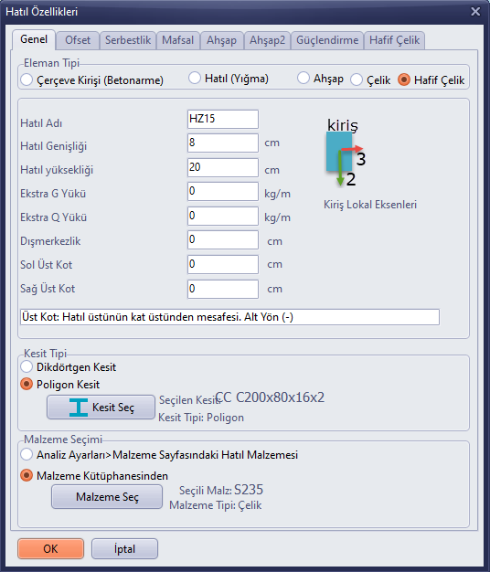
In a cold-formed steel building a header (lintel) is needed above an opening to carry the floor joists and edge strips. The header is drawn above the opening from wall end to wall end as a bond beam (beam); Bond Beam Properties › Member Type: Cold-Formed Steel is selected and a section is assigned from the Cold Formed catalogue with the Select Section button (in this example CC C200x80x22x4, hinged at both ends).
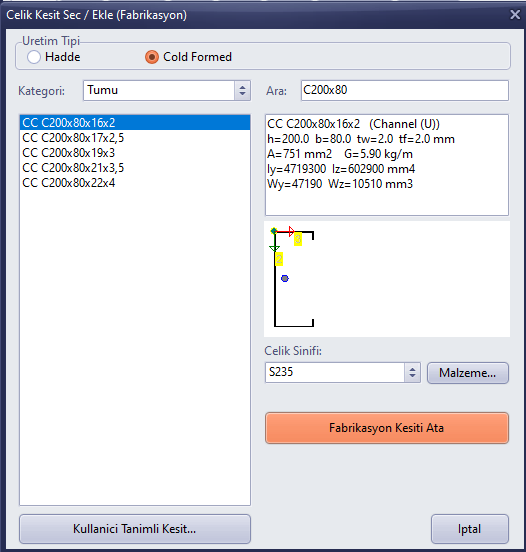
Figure 18 – Prefabricated section selection › Cold Formed (properties of CC C200x80x16x2)
Opening without a header: If floor joists end at a window or door opening and there is no header there, that end of the joist is left unsupported: the finite element solution gives a “rijitlik matrisi tekil” (stiffness matrix singular) warning, and the joists turn out inadequate with excessive moment and deflection. Place a header at every opening in the walls perpendicular to the floor joists (in this example the lines x = 0, x = 5 m and x = 10 m).
8. Cold-formed steel floor
8.1 Drawing the slab and general properties
Each storey is drawn as two rectangular slabs (0–5 m and 5–10 m). In the Slab Properties › General tab the thickness is 2 cm, the sheathing (additional dead) load 30 kg/m², the live load 200 kg/m² (ground floor) / 150 kg/m² (roof). Snow Load: Yes is ticked for the roof slabs. The member type is “Other Slabs”.
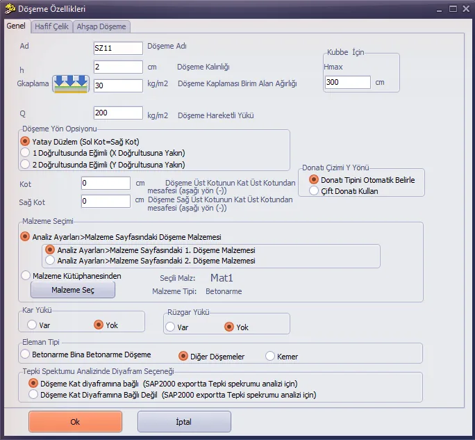
Figure 19 – Slab Properties › General
8.2 “Cold-Formed Steel” tab: strip and floor joist generation
- The Cold-formed steel floor box is ticked.
- Floor joist section: C200x80x16x2 (predefined profile list); Material blank (S235).
- Maximum joist spacing: 390 mm. The program divides 6.00 m into equal parts not exceeding this spacing: 16 spaces × 375 mm, 15 joists. The choice of 375 mm < 400 mm is for the second route of the HCBTİE 7.5 vibration condition.
- Joist direction: parallel to the X axis (joists span 5.00 m between the interior and exterior walls).
- Sheathing: OSB; At least two rows of bridging between joists is ticked.
- Generate / refresh strips and floor joists on OK is ticked and OK is pressed.
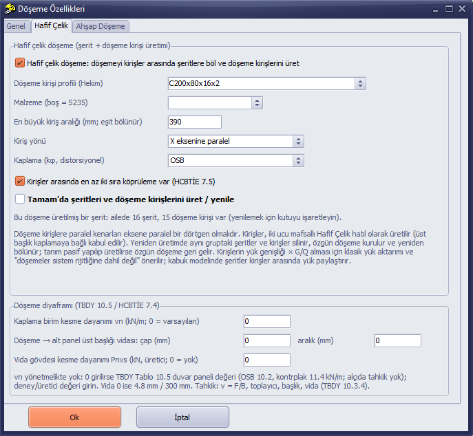
Figure 20 – Slab Properties › Cold-Formed Steel (a generated strip: 16 strips in the family, 15 floor joists)
After generation the slab is divided into 16 strips, and Cold-Formed Steel type floor joists (HZ…, H1…) are placed between the strips. The definition can be changed from the tab of any strip and regenerated with “generate / refresh”; if the box is cleared, the original slab returns.
8.3 Floor diaphragm inputs
In the Floor diaphragm (TBDY 10.5 / HCBTİE 7.4) group at the bottom of the tab, the unit shear strength vn of the sheathing, the diameter/spacing of the screws connecting the floor to the top flange of the lower-storey panel and the screw shank shear strength are entered. If left 0, the TBDY Table 10.5 wall panel value (OSB 10.2 kN/m) is used for vn and 4.8 mm / 300 mm for the screw. The initial design started with these defaults.
8.4 Generated floor joists
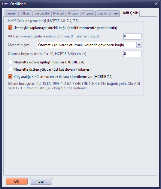
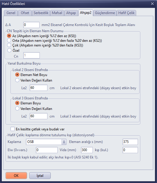
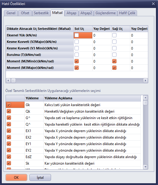
Each generated floor joist is a Cold-Formed Steel bond beam hinged at both ends with M2 + M3. In Bond Beam Properties the section and material, in the Cold-Formed Steel tab the floor joist inputs, and in the Timber2 tab the rotational restraint (kφ) of the sheathing appear as assigned at generation.
9. Analysis: initial design
The Analiz (Analysis) button in the top bar opens the Static Analysis window; Analize Başla (Start Analysis) starts the solution (about 20–35 s in this example). When the analysis finishes, errors and warnings are listed in the list at the bottom; the Seç (Select) button selects the relevant member in the plan.
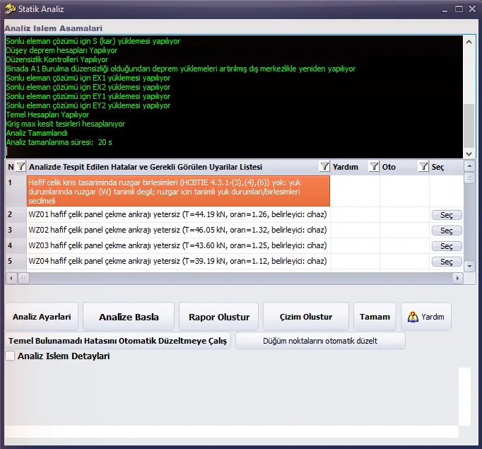
Figure 25 – Static Analysis – warning list of the initial design
The initial design produced 36 output lines. Those important for cold-formed steel are:
Table 2 – Inadequacies of the initial design
| Warning | Count | Example line | Meaning |
|---|---|---|---|
| Tension anchor inadequate (TBDY 10.4.1.1) | 13 | WZ02: T = 46.05 kN, ratio 1.32, governing: device | The uplift force at the panel end (magnified by D = 2) exceeds the 35 kN (25 kN on the 1st floor) strength of the hold-down device. |
| Floor connection inadequate (TBDY 10.5(b), 10.3.4) | 17 | WZ07: V = 33.36 kN > n·Ps = 9 × 2.54 = 22.86 kN (ratio 1.46; 4.8 mm / 300 mm) | The shear with D at the top section of the lower-storey panel exceeds the total strength of the screws connecting the floor to the top flange of the panel. |
| Diaphragm sheathing unit shear inadequate (TBDY 10.5(b)) | 1 | 1. KAT slab, line x = 500 cm: v = 8.55 kN/m > 6.12 kN/m (ratio 1.40) | The force that the roof slab transfers to the interior wall line (F = 51.3 kN, B = 6.00 m) cannot be carried with the default OSB value (vn = 10.2 kN/m). |
Project checklist equivalent of the warnings: The same results are also listed in the “Proje Hata Kontrolleri” (Project Error Checks) page of the report as TBDY 10.4.1.1 (anchor) and TBDY 10.5 / HCBTİE 7.4 (diaphragm) lines.
10. Refining the design
10.1 Floor–panel screws
In each of the four floor families (two per storey), a screw spacing of 150 mm is entered in Slab Properties › Cold-Formed Steel › Floor diaphragm group. A change made in one strip is propagated to all strips of the family on OK. The number of screws doubles (e.g. WZ07: 9 → 18 screws, 22.86 → 45.72 kN).
10.2 Sheathing strength of the roof diaphragm
For the roof (1. KAT) slabs the sheathing unit shear strength vn = 15 kN/m is entered. This value is a manufacturer/test value assumed for this example (e.g. an OSB diaphragm with blocking and close edge screw spacing). The code gives no value for floor diaphragms; in a real project a test value (TBDY Annex 10.C) or the manufacturer’s value must be used.
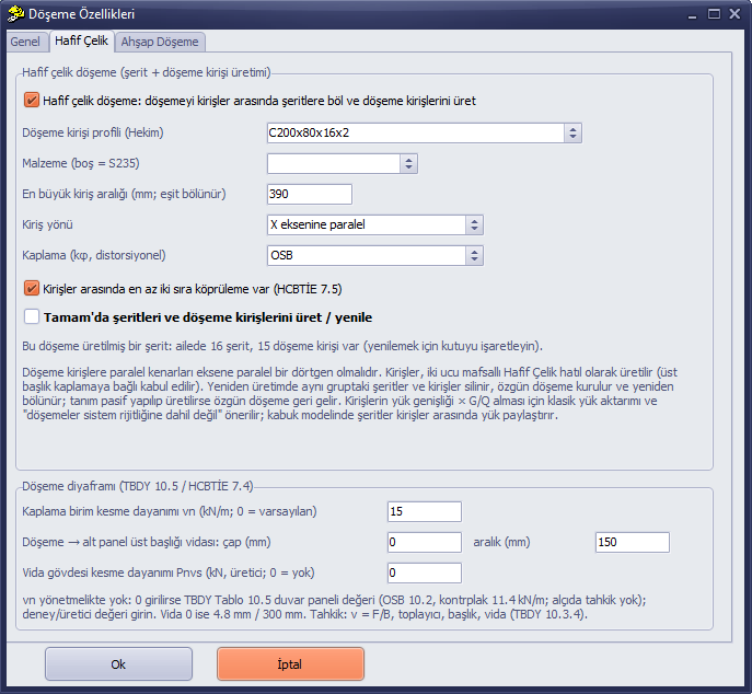
Figure 26 – Cold-Formed Steel tab of the roof slab – refined: vn = 15 kN/m, screw spacing 150 mm
10.3 Tension anchors
All panels are selected and, with Change Multiple Properties (Çoklu Özellik Değiştir), device 55 kN / anchor rod-concrete 60 kN are entered on the ground floor and 35 / 35 kN on the 1st floor in the Cold-Formed Steel Anchor tab. The required number of device-stud screws is given in the report (e.g. 17 screws for WZ01).
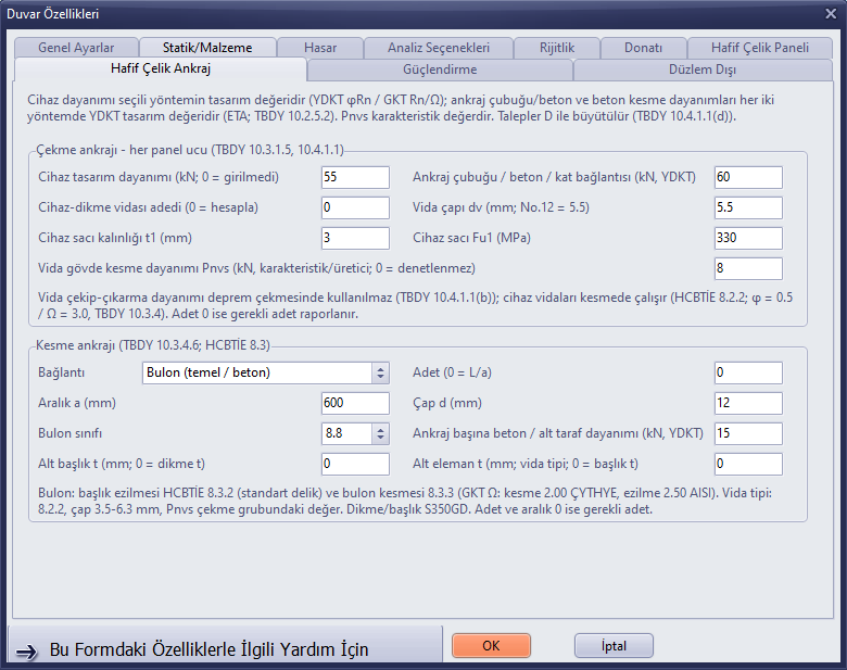
Figure 27 – Cold-Formed Steel Anchor – refined: device 55 kN, anchor rod/concrete 60 kN
10.4 Second analysis
When the analysis is repeated no errors remain; only four information lines are in the list:
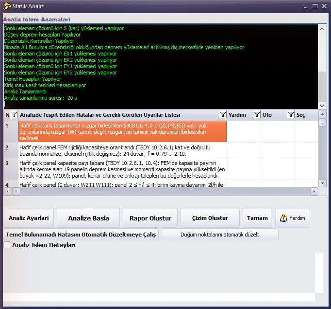
Figure 28 – Static Analysis – warning list of the refined design
Table 3 – Remaining information lines
| Line | Explanation |
|---|---|
| No wind combinations in cold-formed steel beam design | No wind is defined in the load cases (Chapter 4.4). Floor joists and headers were designed with vertical and seismic combinations; the wind check of the studs was made. |
| FEM stiffness scaled to capacity (f = 0.79 … 2.10) | In accordance with TBDY 10.2.6.1 the in-plane stiffness of each panel was scaled in proportion to its shear strength; the total stiffness of the storey does not change. |
| Capacity share floor (largest × 2.22, W109) | The seismic shear of the 19 panels whose FEM shear is below the capacity share was raised to the capacity share; panel, edge stud and anchor demands were calculated with these values. |
| Panel 2 ≤ h/l ≤ 4 (WZ11, W111) | The 1.25 m panels beside the interior door: the unit shear strength was reduced by 2l/h (HCBTİE Chapter 6). |
11. Results
11.1 Seismic loads
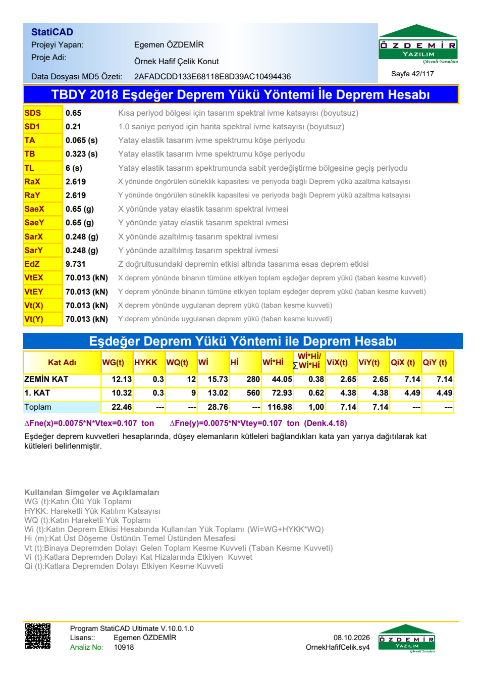
Table 4 – Summary of equivalent seismic load (refined design)
| Quantity | Value |
|---|---|
| SDS / SD1 | 0.65 / 0.21 |
| Period | T = 0.2 s (TBDY 10.2.6.1); calculated Tx = 0.11 s, Ty = 0.09 s for information only |
| Ra / SaR | 2.62 / 0.248 g |
| Seismic mass | 28.76 t (G + 0.3Q) |
| Base shear VtE | 70.0 kN (both directions) |
| Storey forces | Ground floor level 26.0 kN, roof level 43.0 kN |
Torsional irregularity: In the analysis log you may see the line “Binada A1 burulma düzensizliği olduğundan deprem yüklemeleri artırılmış dış merkezlikle yeniden yapılıyor” (since the building has A1 torsional irregularity, the seismic loadings are being repeated with increased eccentricity) (ηbi largest 1.24). In this case the program increases the additional eccentricity automatically.
11.2 Panels, studs and anchors
Table 5 – Selected panels (refined design; ratios are demand/capacity)
| Panel | Section | h (cm) | Intermediate stud | Edge stud | Panel shear | Uplift Td (kN) | Tension anchor | Shear anchor |
|---|---|---|---|---|---|---|---|---|
| WZ01 (2.15 m) | C100x50x15x1.2 | 260 | 0.30 | 0.53 | 0.51 | 44.2 | 0.80 | 0.58 |
| WZ02 (3.65 m) | C100x50x15x1.2 | 260 | 0.34 | 0.62 | 0.40 | 46.1 | 0.84 | 0.55 |
| WZ07 (2.65 m) | C100x50x15x1.2 | 260 | 0.41 | 0.52 | 0.57 | 39.8 | 0.72 | 0.77 |
| WZ12 (4.15 m, interior) | C100x50x15x1.5 | 260 | 0.35 | 0.49 | 0.57 | 32.2 | 0.58 | 0.55 |
| W107 (2.65 m) | C100x50x15x1.2 | 260 | 0.28 | 0.34 | 0.59 | 27.3 | 0.78 | 0.43 |
| W111 (1.25 m, interior) | C100x50x15x1.5 | 260 | 0.10 | 0.28 | 0.81 | 28.2 | 0.81 | 0.45 |
| W112 (4.15 m, interior) | C100x50x15x1.5 | 260 | 0.16 | 0.33 | 0.69 | 32.5 | 0.93 | 0.50 |
The intermediate and edge stud ratios are the larger of the axial compression and, for exterior walls, the wind combination (P/Pd + M/Md). The edge stud demand includes the overturning force magnified by D (TBDY 10.4.1.1(a)). Since there is no gypsum board, the gypsum share of TBDY 10.2.7.2 is 0% in every storey and direction.
11.3 Floor joists and headers
Table 6 – Beam results (most unfavourable)
| Member | Section | M / Md | Deflection | Other |
|---|---|---|---|---|
| Floor joist, ground floor (HZ08) | CC C200x80x16x2 | 4.82 / 8.64 kNm = 0.56 | 0.88 cm ≤ L/300 = 1.67 cm | fn = 8.2 Hz; web crippling 0.59 |
| Floor joist, roof (H137) | CC C200x80x16x2 | 4.36 / 8.64 kNm = 0.50 | 0.73 cm | fn = 8.7 Hz |
| Header, ground floor (HZ07, 1.50 m) | CC C200x80x22x4 | 3.44 / 19.59 kNm = 0.18 | 0.03 cm | — |
| Header, 1st floor (H107, 1.50 m) | CC C200x80x22x4 | 2.91 / 19.59 kNm = 0.15 | 0.02 cm | — |
11.4 Floor diaphragm
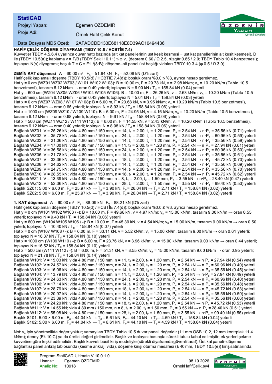
At each floor level the wall lines are established and the line force is found according to TBDY 4.5.6.4 (top-section shear of the lower-storey panels − bottom-section shear of the upper-storey panels, with D). In the refined design the largest sheathing ratio is 0.95 (roof, line x = 500 cm, v = 8.55 kN/m ≤ 0.6 · 15 = 9.0 kN/m), the largest connection ratio is 0.73; the collector and chord ratios are below 0.14.
11.5 Finite element model
In the finite element model the panels appear as bar wall elements, and the floor joists and headers as hinged bars; the wall bases are supported. The model can be displayed in the 3D panel with the Finite Element System Display Options (right bar).
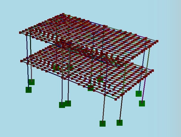
Figure 29 – Finite element bar model (supports in green)
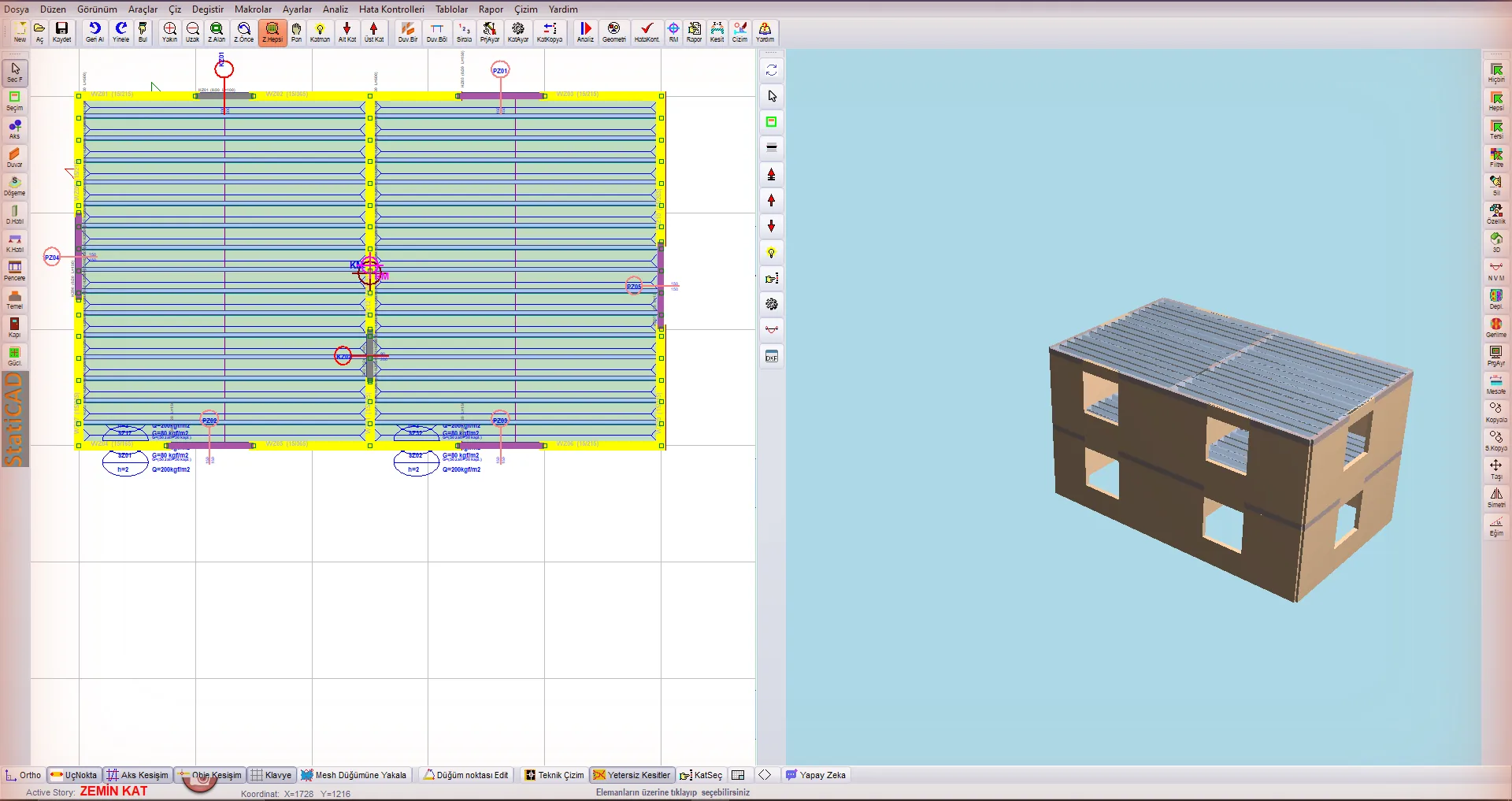
Figure 30 – Main screen after the analysis of the refined design
12. Calculation report
- The Rapor (Report) button in the top bar opens the Report Selection.
- In the tree the Cold-Formed Steel Member Reports group and its child nodes are ticked: Cold-Formed Steel Panel Design (TBDY2018), Cold-Formed Steel Stud Design (EWM), Cold-Formed Steel Beam Design (EWM). The group comes unticked by default.
- The report is prepared with Create All Selected Reports and the preview opens; from there it can be printed or saved as PDF.
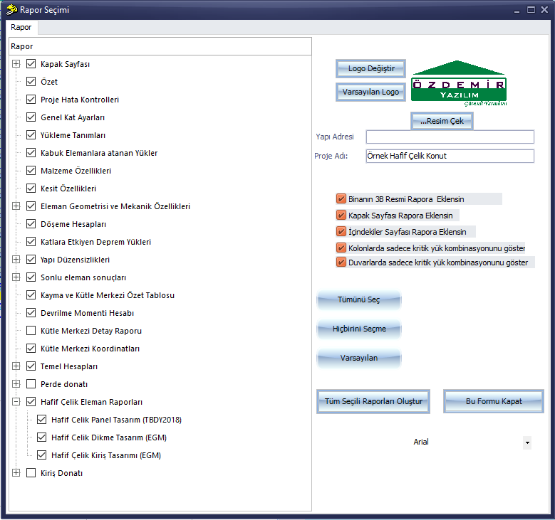
Figure 31 – Report Selection: Cold-Formed Steel Member Reports and sub-reports
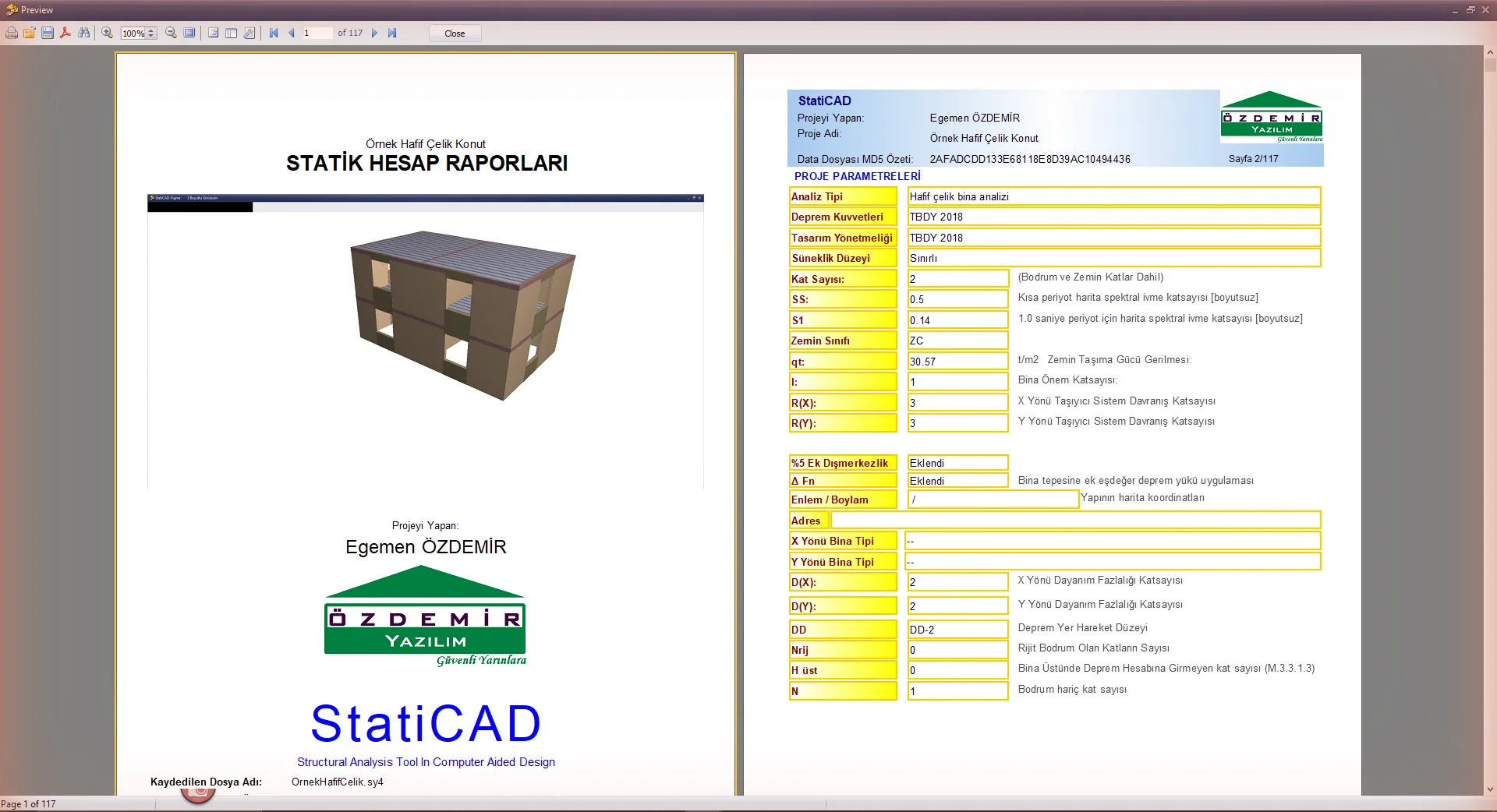
Figure 32 – Report preview window (117 pages)
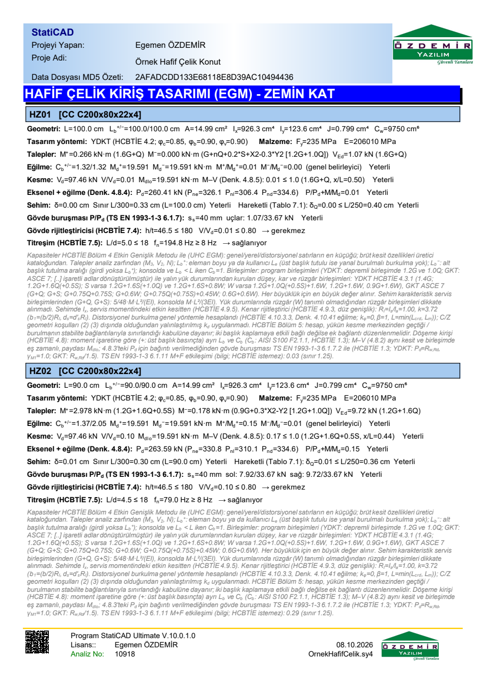
Selected pages of the example report:
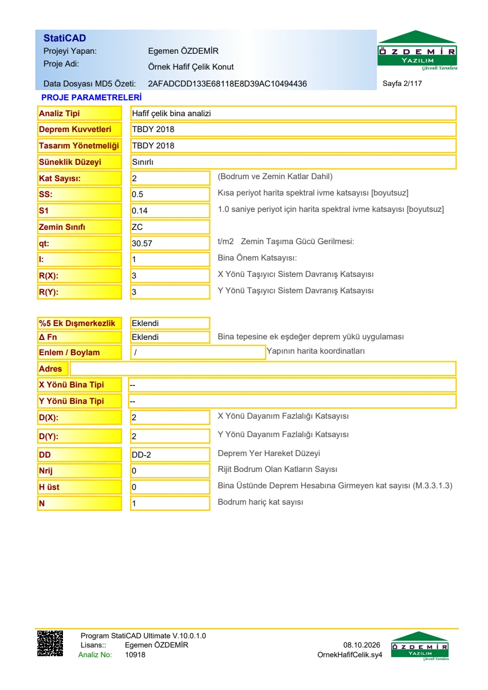
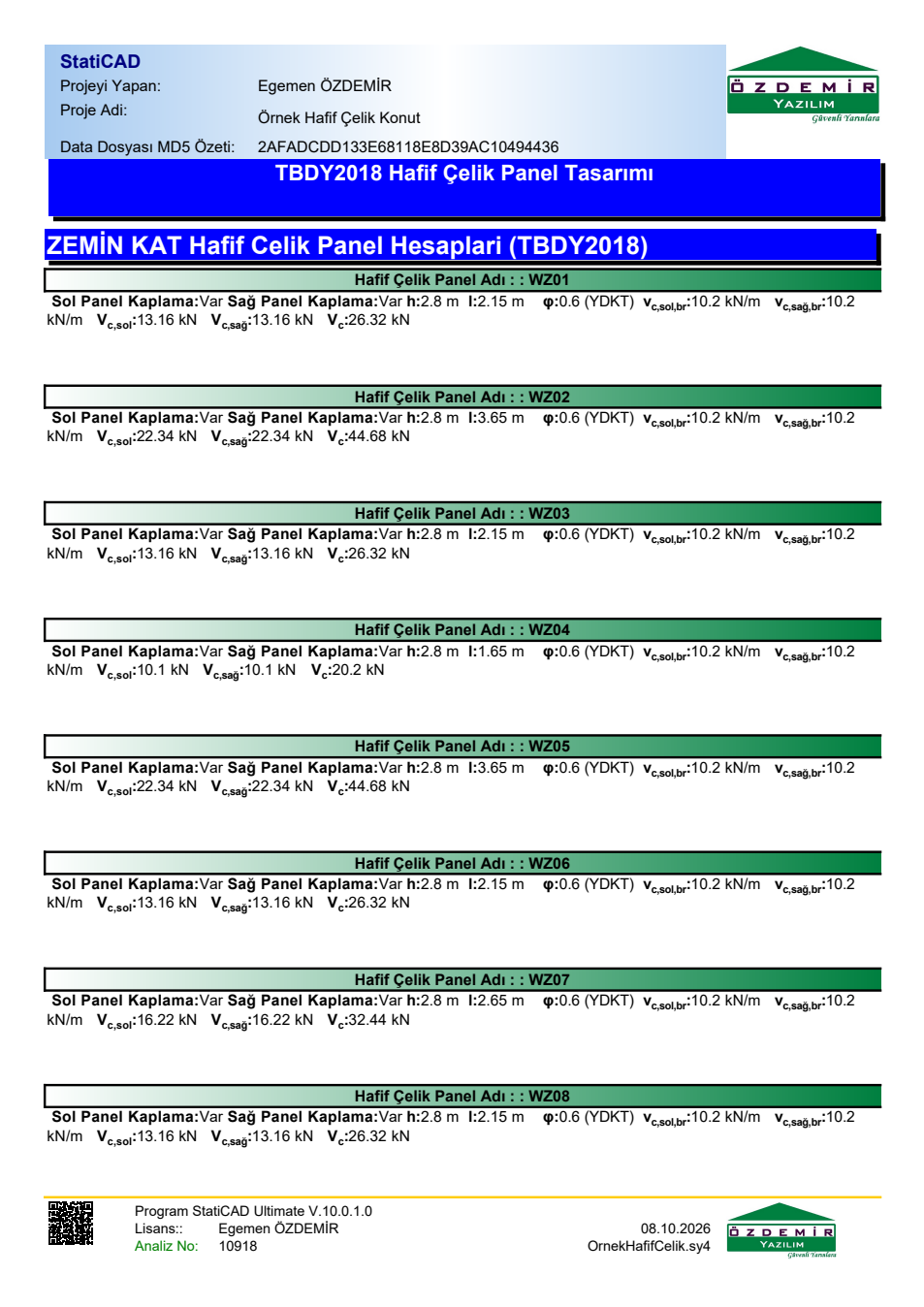
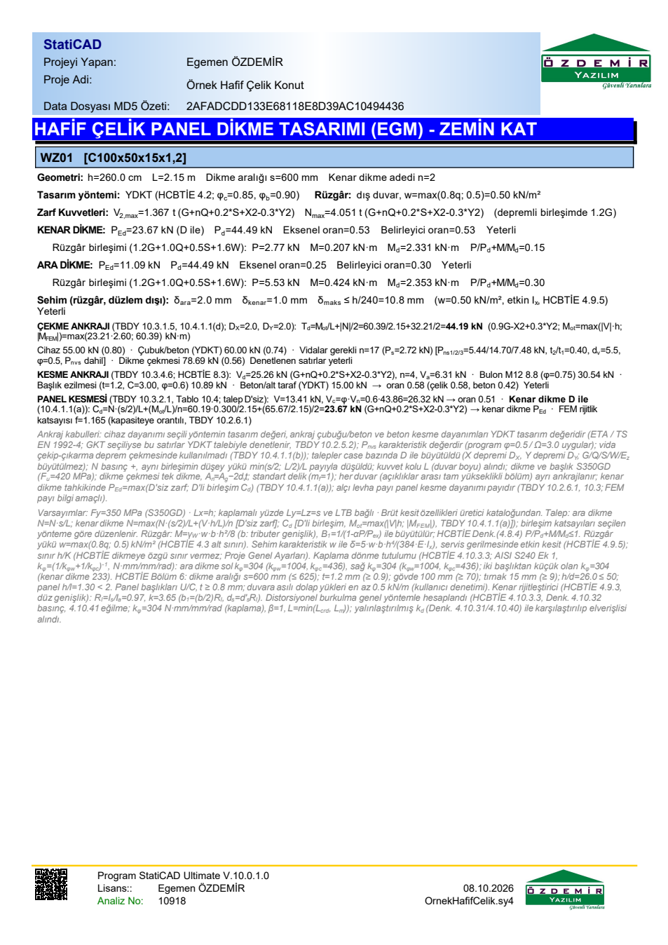
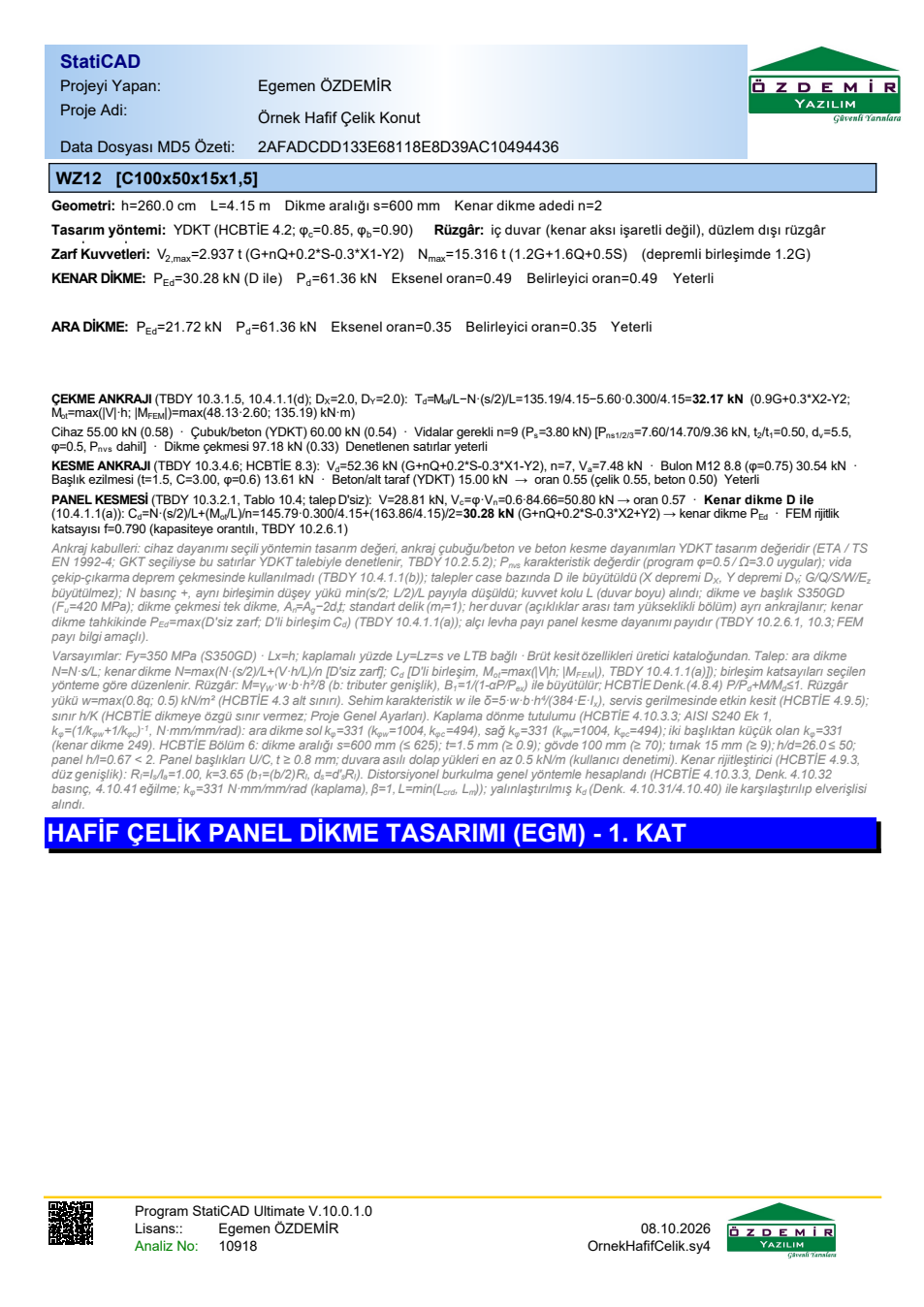
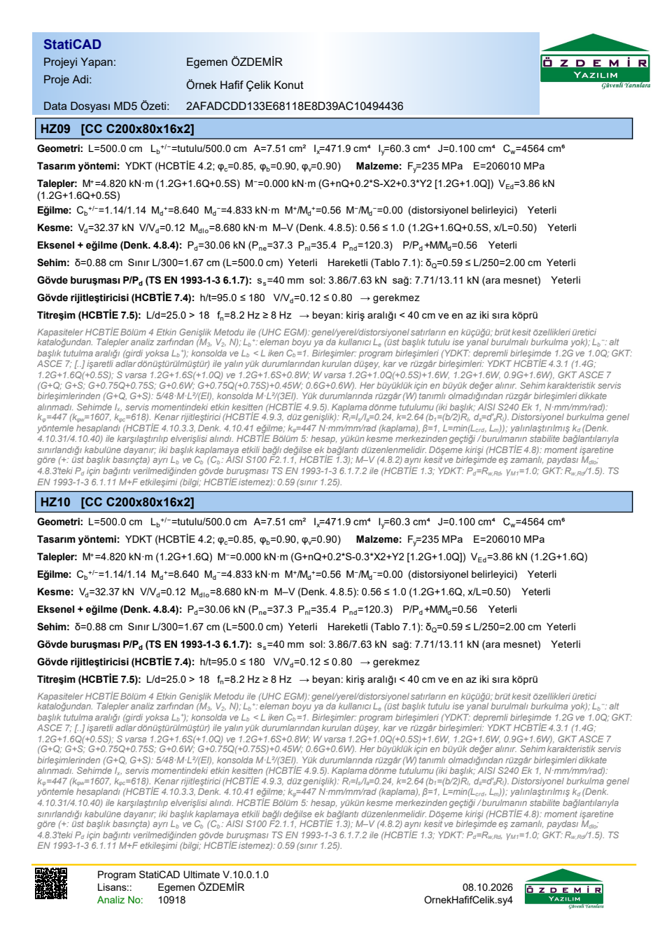
Unnecessary pages: The “Slab Calculations” node also prints the reinforced concrete slab tables for cold-formed steel strips; these pages are meaningless for a cold-formed steel floor, so the node can be left unticked.
13. Drawings
The Çizim (Drawing) button in the top bar opens the Drawing Selection window. The sheet types and the storeys to be drawn are selected; Draw Storey Plans produces the storey and formwork plans, and Draw Project with Elevations produces all sheets including elevations in the StatiCAD-CivilDraw editor.
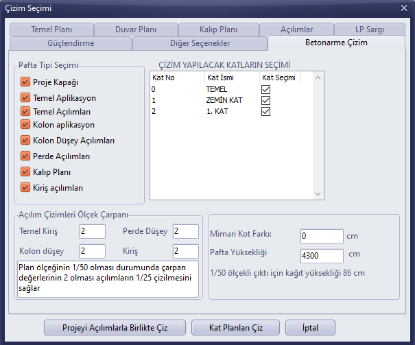
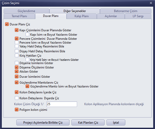
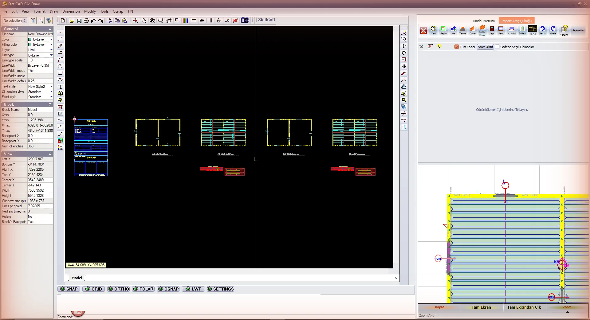
Figure 43 – StatiCAD-CivilDraw: cover, storey wall plans and formwork plans
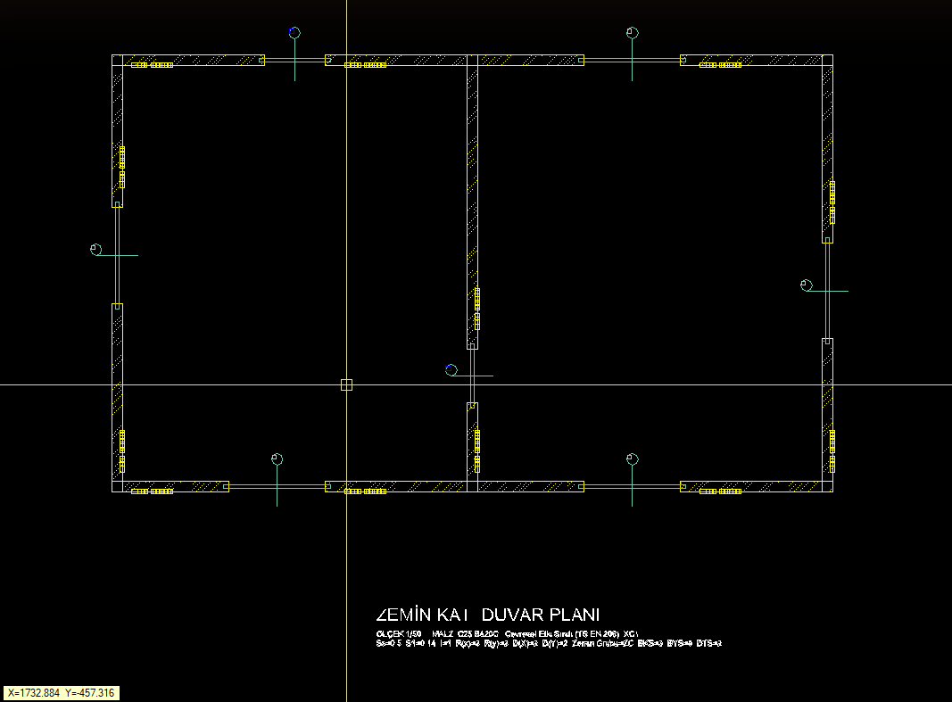
Figure 44 – Ground floor wall plan (panels, openings, grid lines)
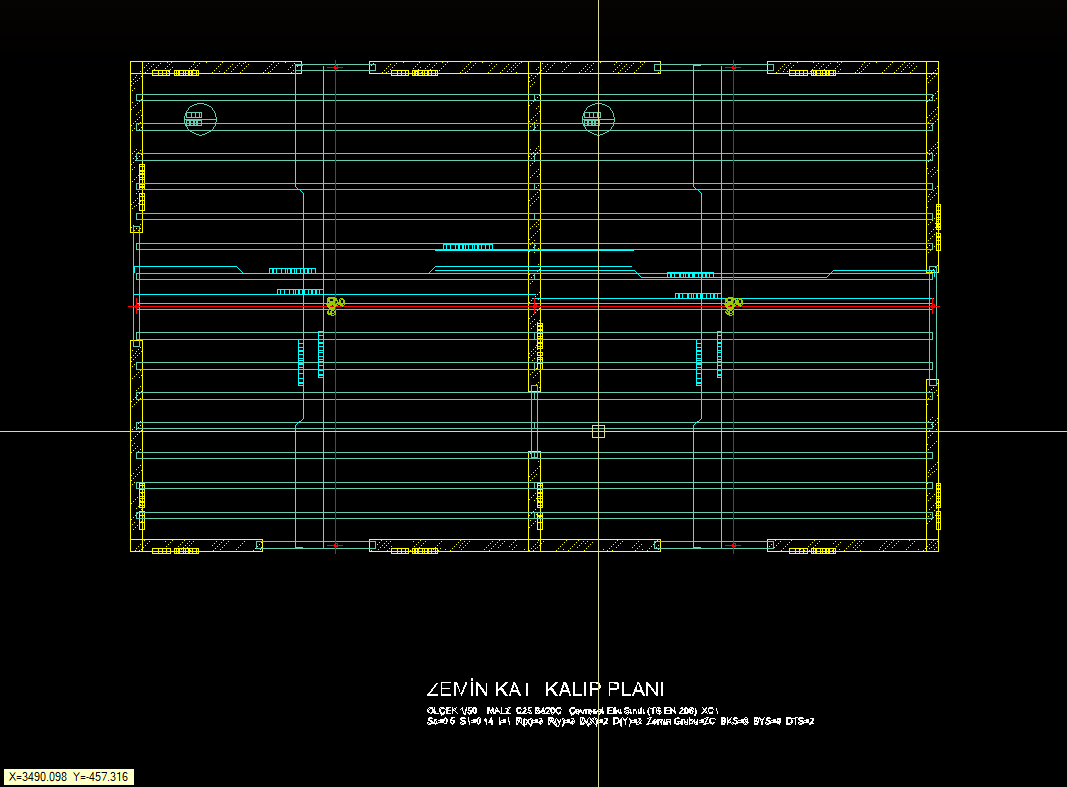
Figure 45 – Ground floor formwork plan (floor joists and strips)
Scope of the drawings: The drawing module does not produce sheets specific to cold-formed steel (stud layout, floor joist setting-out, anchor and connection details); the wall and formwork plans are general plan drawings. Reinforced concrete reinforcement lines tied to the slab calculation axes may also appear in the formwork plan; these do not apply to a cold-formed steel floor. The material line in the sheet title (C25 etc.) is the general project material.
14. Points to note and known limits
| Subject | Explanation / action |
|---|---|
| Offset boxes (Chapter 4.1) | Rigid diaphragm + beam axis offset gives the floor joists an artificial axial force in the FEM; the program subtracts this share in cold-formed steel beam design, so the boxes do not need to be cleared. The raw axial force appears in the FEM beam result tables. This correction does not exist for heavy steel beams. |
| Wall weight (Chapter 6.3) | Selecting “Panel in Cold-Formed Steel” sets the thickness to 15 cm and BHA to 300 kg/m³; correct them if the actual values of the panel are different. |
| Panel Type (Gypsum Board / Other) | This selection in the Project General Settings has no effect on the calculations; the sheathing is entered per wall. |
| Wind load case (Chapter 4.4) | There is no wind in the TBDY combination list; defined load cases are needed for the wind combinations of cold-formed steel beams/columns. The stud wind check is made separately with q. |
| Header (Chapter 7) | Place a header at every opening where floor joists end; otherwise the joist end is left unsupported. |
| Diaphragm vn (Chapter 10.2) | The code gives no value; if 0 is entered, the wall panel value is used by analogy. Enter a test or manufacturer value. |
| Foundation | No foundation is drawn in this example. In a cold-formed steel building the foundation internal forces are magnified by D (TBDY 10.4.1.2); for this, “Finite Elements – Structure and Foundation Combined Analysis” must be selected in the Project General Settings. |
| Other limits | See the “Assumptions and limits” section of the article Theoretical Basis of Cold-Formed Steel Design. |
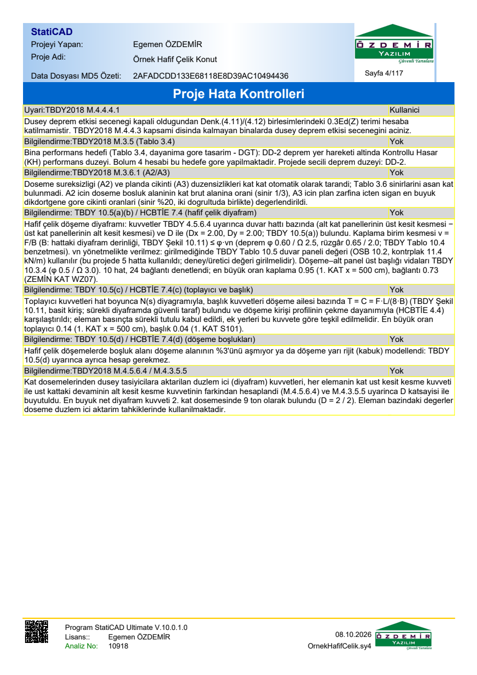
Figure 46 – Report › Project Error Checks (TBDY 10.5 diaphragm and M.4.5.6.4 lines)