Import and Export
1. Creating a Model from an Architectural Plan (Import 2D)
The File › Import 2D command or the DWG Import icon on the start screen opens the TechnicDraw editor together with the Import Toolbar. The architectural DWG/DXF plan is opened in the editor, and by selecting pairs of lines it is converted into wall, door, window, beam, tie column, grid line and foundation elements.
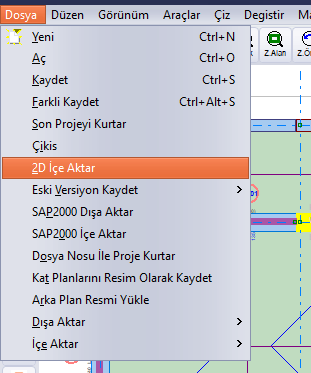
Location of the File › Import 2D command
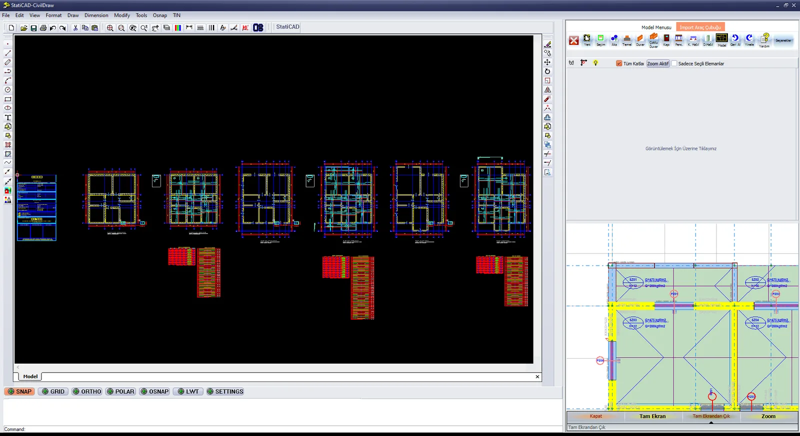
Import 2D: TechnicDraw and the Import Toolbar on the right

Import Toolbar: Yeni (New), Seçim (Selection), Aks (Grid Line), Temel (Foundation), Duvar (Wall), Çoklu Duvar (Multiple Walls), Kapı (Door), Penc. (Window), K. Hatıl (Bond Beam), D.Hatıl (Tie Column), Model, Geri Al (Undo), Yinele (Redo), Yardım (Help), Seçenekler (Options)
- In the editor, open the architectural DWG/DXF file with File › Open (if it is not visible, save the file again in DWG 2007 format).
- Simplify the drawing, turn on object snapping (Osnap, Endpoint) and move the drawing so that the reference corner is at (0,0).
- Check the units (cm) with Tools › Distance; scale if necessary.
- In StatiCAD, make the storey settings and select the target storey.
- On the Import Toolbar, select the Duvar (Wall) command, set the wall properties and select the two edge lines of the wall; the imported lines turn red. Apply the same method for doors, windows, beams, tie columns and foundations.
- In StatiCAD, correct open corners with Intersect 2 Elements and fragmented walls with Merge Walls, and create the grid lines.
Details: Creating a static model from a DWG/DXF file.
2. IFC (BIM) Import and Export
In the Hybrid and Ultimate editions, the model can be exported in IFC2x3 format and can be imported from IFC files (including SAP2000 structural models).
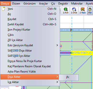
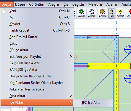
- Export: Run the File › Export › ifc command, specify the file name and location in the Export IFC window and save. At the end of the operation, the message “IFC dışa aktarıldı” (IFC exported) appears. Export is disabled in the demo edition.
- Import: Run the File › Import › Import IFC command. The program asks for a confirmation stating that the elements will be added to the current project; then the .ifc file is selected and the storeys and elements are created.
Note: IFC import adds to the open project. To avoid corrupting the existing model, open a new project before importing.
Details: IFC (BIM) import and export.
3. SAP2000 Transfer
File › Export SAP2000 or the Sap2000 Options icon on the start screen opens the SAP2000 Export Options window. The program edition to transfer to, the wall support option, the support location, the diaphragm options, the maximum number of modes, the target dynamic participation ratio and the area element options are specified; the model is transferred with the Export to SAP2000 button. A licensed SAP2000 must be installed on the computer for the transfer; the transfer does not work with trial installations. File › Import SAP2000 opens the StatiCAD-Saptrans window for data exchange with SAP2000.
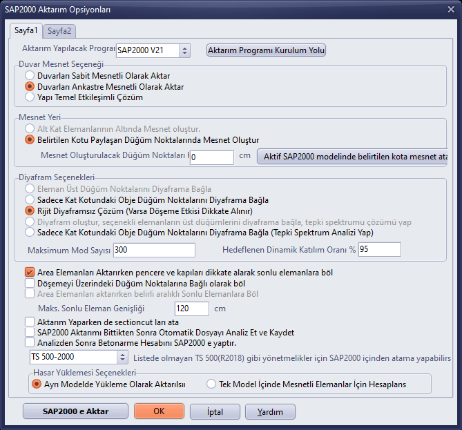
SAP2000 Export Options window
Details: Points to consider in integrated analysis with StatiCAD and SAP2000.