Modelling Tools
1. General Rules
- Elements are drawn on the active storey. To change the storey, use the Lower Storey / Upper Storey buttons, the Ctrl+Down/Up keys or the KatSeç (Select Storey) window.
- Foundations are drawn only on the TEMEL (foundation) storey (storey 0).
- Most drawing commands first open a properties dialog or a tool window. After the values are entered and OK is pressed, points are marked in the drawing area.
- The hint line announces the points expected by the command (e.g. “Temelin ilk ve ikinci noktasını işaretleyin” – Mark the first and second points of the foundation).
- Right-click finishes the drawing command and closes the open tool windows; Esc returns to selection mode and clears the selections.
- When snapping is on, points snap to the ends of existing elements, grid line intersections and nodes.
- Drawn elements are selected and edited with the Change … Properties command of the right-click menu (see “Selection and Editing”).
- Dialog titles may vary with the building type: for example, the beam dialog is named Bond Beam Properties in a masonry building, and the column dialog is named Tie Column Properties.
2. Grid Line
The Grid Line button on the left toolbar or Draw › Grid Line (Shift+A) opens the Grid Line Drawing tool window. The window contains grid line type icons and a Distance box; grid lines are drawn by marking two points in the drawing area. For an inclined grid line, ea can be used in the command line.

Grid Line Drawing tool window
If walls and beams were created without drawing grid lines, the Modify › Create Grid Line If Missing command automatically creates grid lines under the elements. Grid lines are also visible on the other storeys and provide snap points; for this reason it is useful to use the command before drawing the foundation.
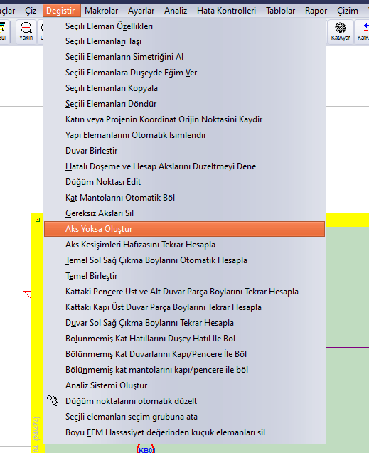
Location of the Modify › Create Grid Line If Missing command
Details: Creating an inclined grid line and a grid line parallel to an inclined grid line.
3. Wall and Shear Wall
The Wall button on the left toolbar, Draw › Wall (Shift+W) or w in the command line opens the Wall Properties dialog. The Element Type group contains the options Masonry Wall, Reinforced Concrete Shear Wall, Reinforced Concrete Basement Shear Wall, Timber Shear Wall, Infill Wall (Flexible, Jointless), Infill Wall (Flexible, Jointed), Log Wall and CLT Shear Wall (Cross-Laminated). On the General Settings tab, the wall name, wall width (cm), bond beam height above the wall, lower and upper elevations, extra dead (G) and live (Q) loads, eccentricity and shear wall position are defined.
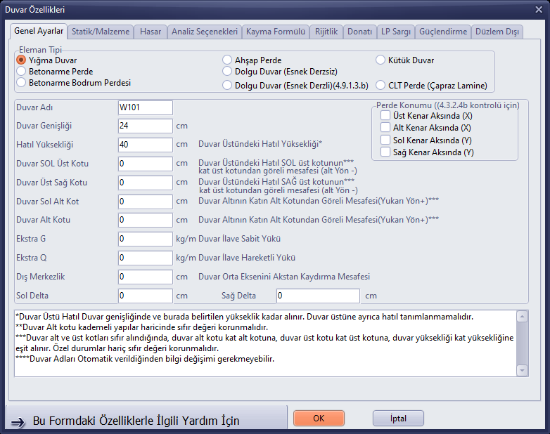
Wall Properties – General Settings tab
- Click the Wall button (or type
win the command line and press Enter). - Set the element type and the wall width, and click OK.
- The hint line shows “Duvarın ilk ve ikinci noktasını işaretleyin” (Mark the first and second points of the wall). Click the start and end points or type the coordinates in the command line.
- In continuous drawing mode, continue with the next corner. Right-click to finish.
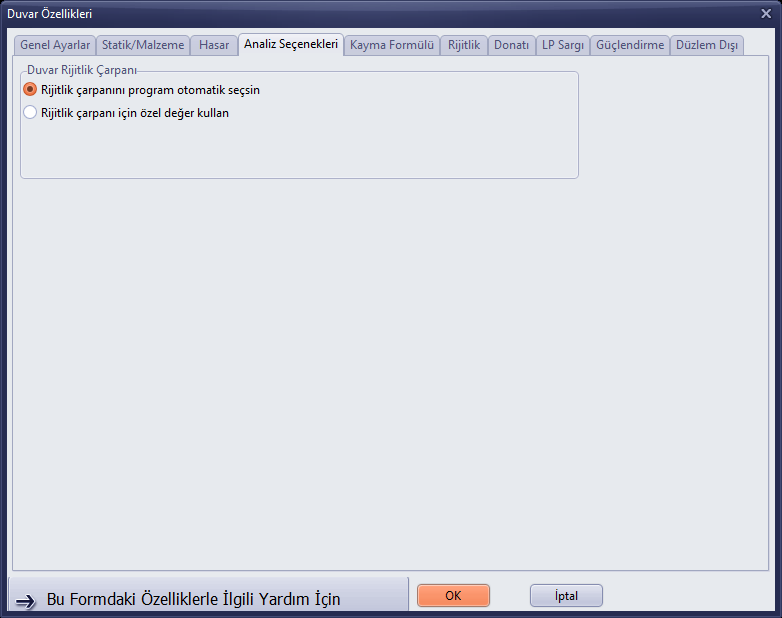
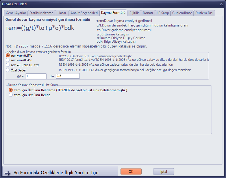
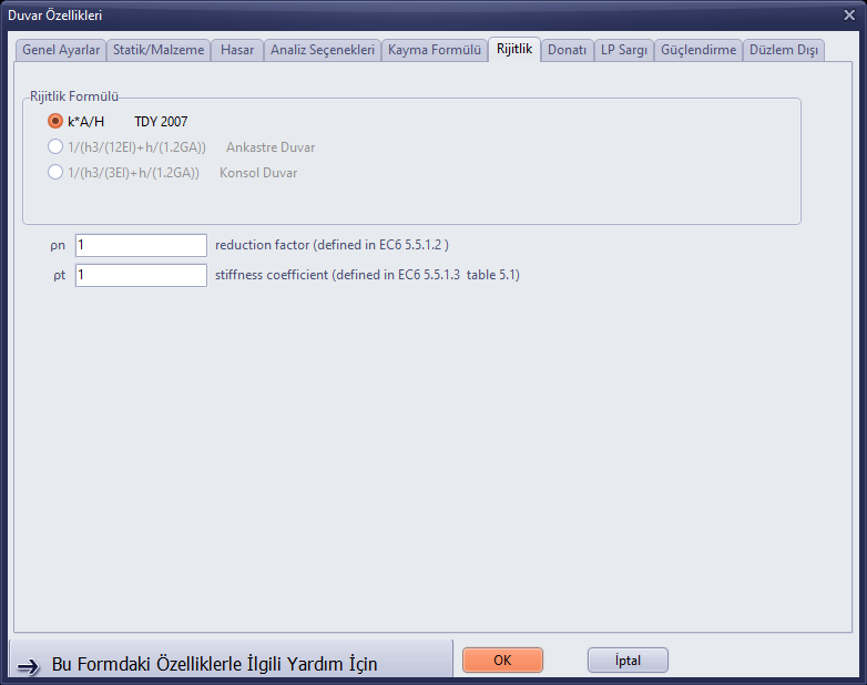
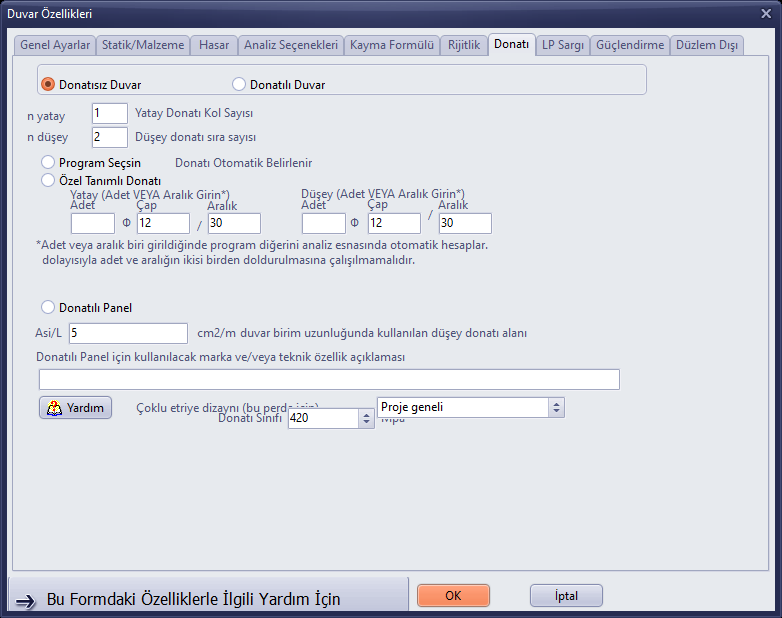
Other tabs of the Wall Properties dialog
| Tab | Content |
|---|---|
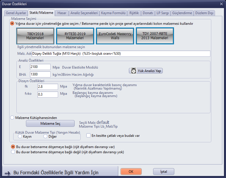
| Static/Material | Material selection (TBDY2018, RYTEİE-2019, EuroCode6, TDY2007 material buttons or the material library), modulus of elasticity, compressive and shear strengths. |
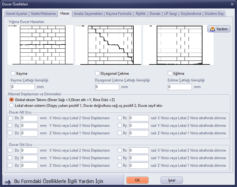
| Damage | Shear, diagonal tension and crushing damage, and support displacements at the wall ends. |
| Analysis Options | Letting the program select the stiffness multiplier or entering a custom value. |
| Shear Formula | Wall allowable shear stress formula and the upper limit of the shear capacity. |
| Stiffness | Wall stiffness formula (e.g. k*A/H) and reduction factors. |
| Reinforcement | Reinforced wall and reinforced panel options. |
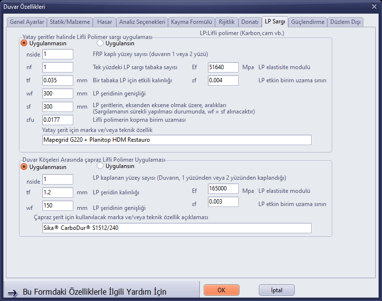
| FRP Wrapping | Strengthening with fibre-reinforced polymer (FRP) wrapping: horizontal strips and diagonal application between corners. |
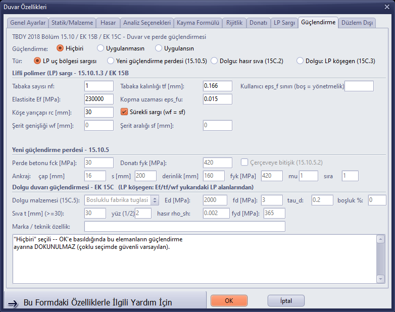
| Strengthening | TBDY 2018 Section 15.10 / Annex 15B / Annex 15C strengthening options. |
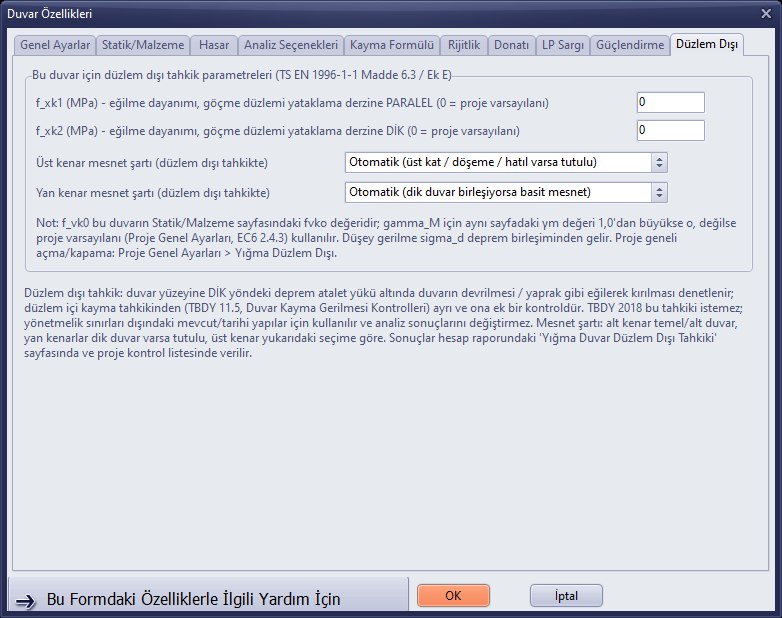
| Out-of-Plane | Out-of-plane check parameters of the masonry wall. |
Out-of-Plane
4. Slab
The Slab button on the left toolbar opens the Slab Drawing tool window. The window contains slab type icons (rectangle, Polygon, Curved, Circle, Dome, Mesh), the finish load (G, kg/m²), live load (Q, kg/m²), thickness (H, cm), Elevation fields and the RC Calculation Axis (Draw, Edit, Delete) buttons. For a rectangular slab, the hint line says “Döşemenin sol üst ve sağ alt noktasını işaretleyin” (Mark the upper left and lower right points of the slab); clicking two opposite corners is sufficient.

Slab Drawing tool window

Hint line in slab mode
Draw › Slab (Shift+S), on the other hand, opens the Slab Properties dialog: slab name, thickness, finish weight, live load, slab direction option, elevations, reinforcement drawing directions, material, snow and wind load options and the diaphragm option in the response spectrum analysis.
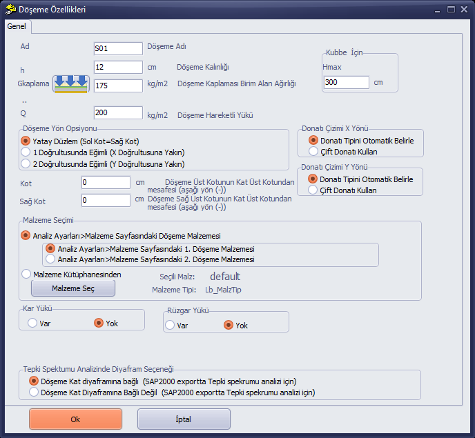
Slab Properties dialog
5. Beam and Bond Beam
The K.Hatıl (Bond Beam) button on the left toolbar or Draw › Beam / Bond Beam (Shift+H) opens the Bond Beam Properties dialog (in reinforced concrete buildings the title is Beam Properties). The Element Type is selected as Frame Beam (Reinforced Concrete), Bond Beam (Masonry), Timber or Steel; the name, width, height, extra loads, eccentricity, left/right top elevations, section type and material are entered. After OK, the hint becomes “Kiriş hatılın ilk ve ikinci noktasını işaretleyin” (Mark the first and second points of the beam/bond beam).
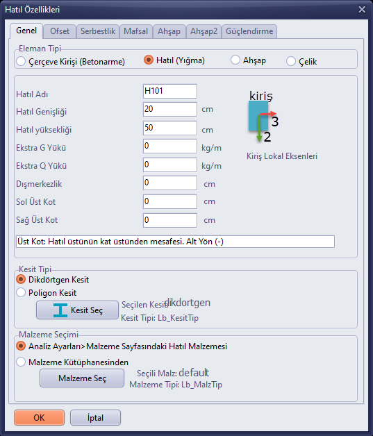
Bond Beam Properties – General tab
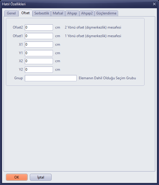
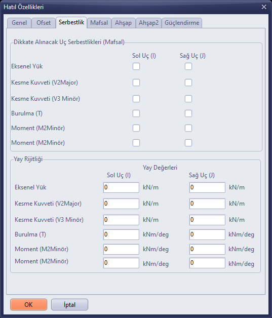
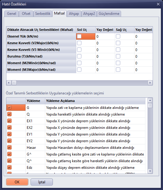
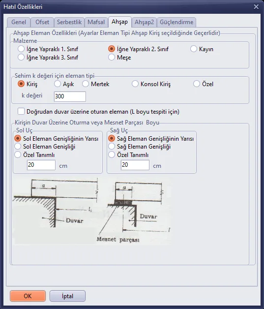
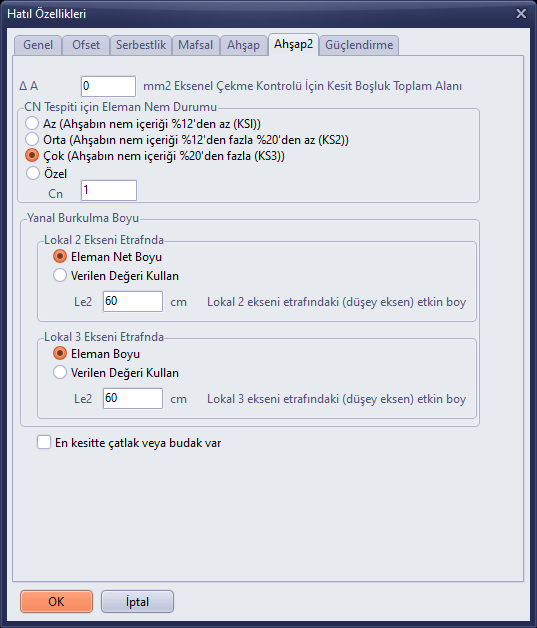
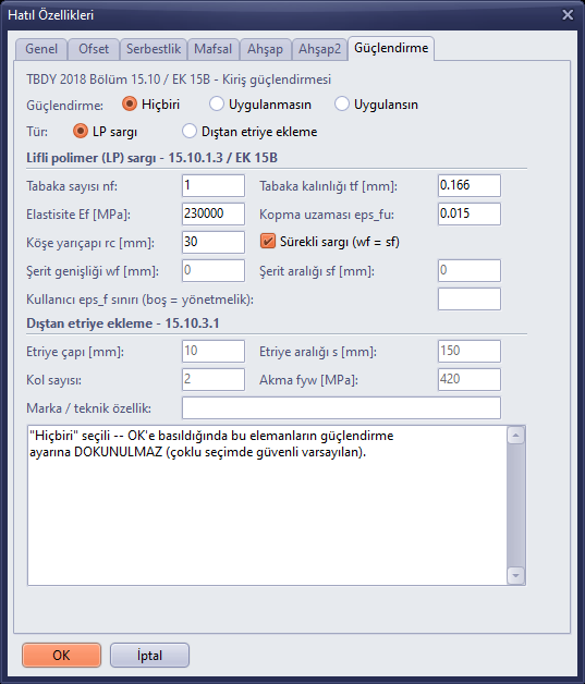
Other tabs: Offset (end offsets and selection group), Releases (end releases and spring stiffnesses), Hinge (hinge definition by loadings), Timber and Timber2 (timber element and buckling parameters), Strengthening (TBDY 15.10 / Annex 15B beam strengthening).
6. Tie Column and Column
The D.Hatıl (Tie Column) button on the left toolbar opens the Tie Column Drawing tool window (Distance, direction icons, Thickness, Length, Eccentricity). The hint line says “İlk tıklama ile düşey hatılın referans noktasını, ikinci tıklama ile doğrultusunu belirtin” (Specify the reference point of the tie column with the first click and its direction with the second click).

Tie Column Drawing tool window
Draw › Tie Column (Shift+D) opens the Tie Column Properties dialog. Element Type: Reinforced Concrete Column, Timber Column/Stud, Steel, Tie Column or Truss Post. d is the thickness in direction 3, L is the length in direction 2, DNM is the distance from the node and e is the eccentricity; the elevations, section type and material are also on this tab. The other tabs are Stiffness, Hinge, Timber and Strengthening.
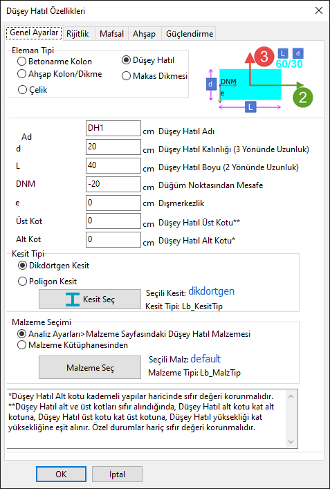
Tie Column Properties – General Settings tab
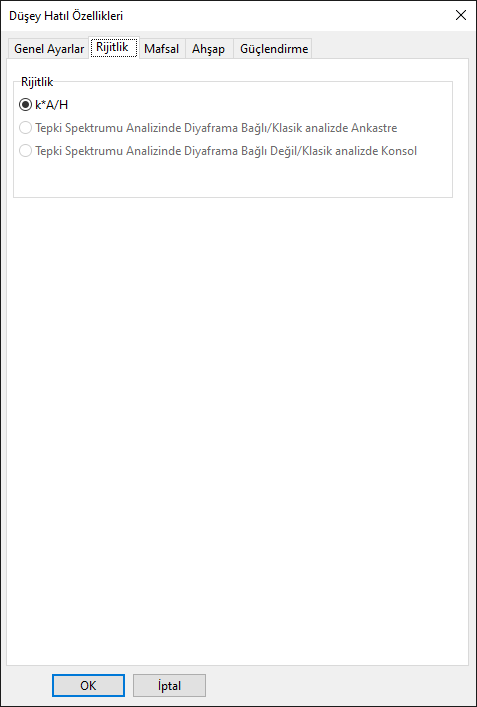
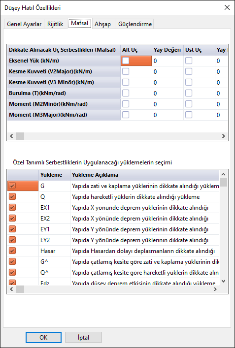
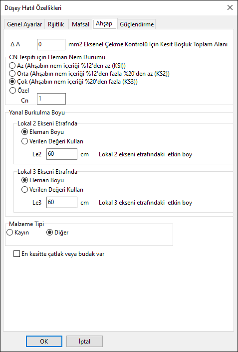
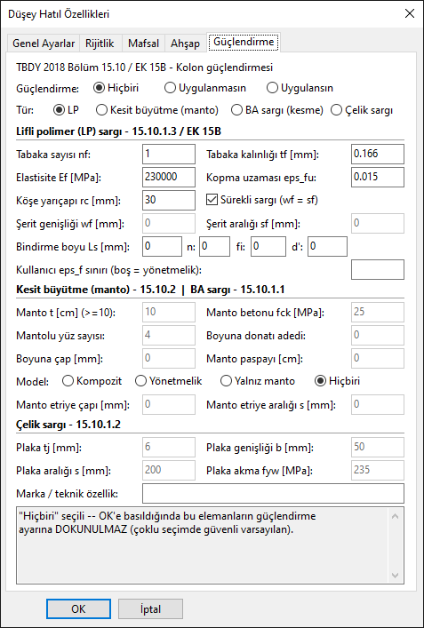
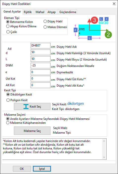
Properties of an existing reinforced concrete column (DHB07) – opened with right-click › Change Properties
7. Door and Window
The Door and Window buttons on the left toolbar (Shift+K, Shift+P) open the corresponding tool windows. The windows contain Distance (distance from the reference point), direction icons, Width, Height, Eccentricity and, for the window, also the Hparapet (parapet height) fields. The default values are 90 × 200 cm for the door, 130 × 150 cm for the window and 90 cm for the parapet.


- Click the Door (or Window) button and set the values in the tool window.
- The hint line shows “İlk tıklama ile kapının referans noktasını, ikinci tıklama ile doğrultusunu belirtin” (Specify the reference point of the door with the first click and its direction with the second click).
- Click on one end of the wall (the reference point).
- Click on a second point on the same wall in the direction in which the opening will be placed. The opening will be placed at a distance equal to Distance from the reference point.
- Repeat the steps to add other openings; right-click to finish.

Hint line in window mode
8. Foundation
Foundations are drawn only on the TEMEL storey. If the Foundation button is pressed while on another storey, a notification appears at the bottom left corner of the screen for a few seconds:
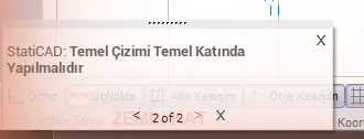
“Temel Çizimi Temel Katında Yapılmalıdır” (Foundation drawing must be done on the foundation storey) notification
- Go to the TEMEL storey with Ctrl+Down Arrow, the Lower Storey button or the KatSeç window. The active storey label must read TEMEL.
- Click the Foundation button. In the Foundation Properties dialog, set the foundation name, width (default 80 cm), height (40 cm), left/right projection (delta), eccentricity, top elevation, element type (Reinforced Concrete Continuous Foundation or Masonry Wall Foundation), section and material, and click OK.
- The hint becomes “Temelin ilk ve ikinci noktasını işaretleyin”. Click the two end points for each foundation; each foundation is drawn with its own two clicks.
- After drawing foundations under all load-bearing walls, finish the command by right-clicking.
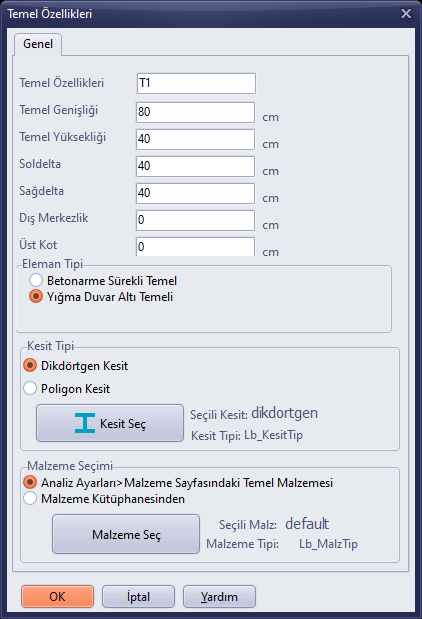
Foundation Properties dialog
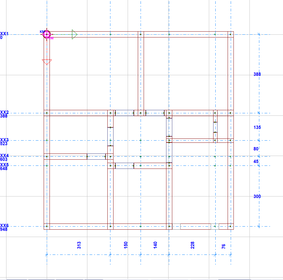
TEMEL storey of the sample project (red lines are the foundation boundaries)
Tip: On the TEMEL storey, the walls of the storey above are shown with thin red lines and the corner nodes with green dots; place the foundation ends by clicking on these nodes. If you get the “TEMEL MODELLEMESİ YAPINIZ” (Model the foundation) warning in the analysis, check that there is a foundation under every wall.
9. Strengthening Jacket
The Gücl. (Strengthening) button on the left toolbar or m in the command line opens the Wall Strengthening Jacket Properties dialog (in editions that include performance assessment and strengthening). The jacket name, the thickness of the wall to be jacketed, the wall–jacket eccentricity, the left/bottom and right/top projection lengths, the concrete jacket thickness, the elevations, the Jacket Direction (Upper/Left Face Cladding or Lower/Right Face Cladding) and the material are entered. After OK, the hint becomes “Mantonun ilk ve ikinci noktasını bağlı duvar aksında işaretleyin” (Mark the first and second points of the jacket on the axis of the connected wall).
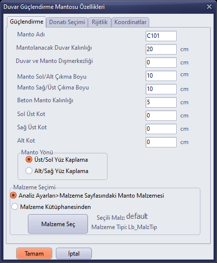
Wall Strengthening Jacket Properties – Strengthening tab
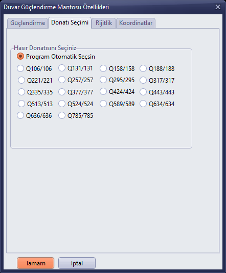
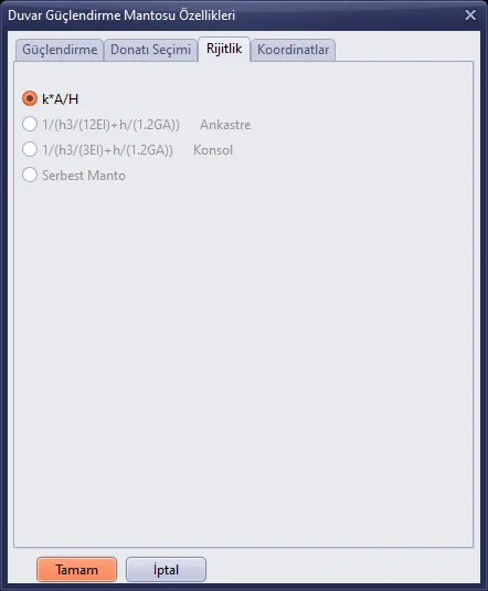
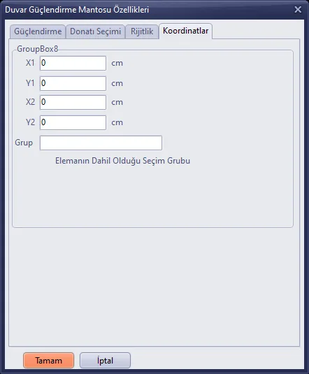
Coordinates
Details: Strengthening of masonry buildings in the StatiCAD program.
10. Selection and Editing
Selection Methods
- In Seç F (Select F) mode, clicking an element toggles its selection; several elements can be clicked one after the other.
- In Seçim (Selection) mode, a frame is drawn with the left button and the elements inside the frame are selected.
- All (Ctrl+A), None (Ctrl+Shift+A) and Invert (Ctrl+I) change the selection on the active storey in bulk.
- The Filter button is used to select elements by type and to create selection groups.
- The Esc key clears all selections.
Find Structural Element
To find an element whose name is known, use Edit › Find Object (Ctrl+F) or Bul (Find) on the top bar.

Find Structural Element window
- Open the window with Ctrl+F and type the exact name of the element in the box (e.g.
PZ01). - Tick the Search on this storey or Search on All Storeys option.
- Click Find and Select. The element is selected and the view is zoomed to the element.
- Exit with Close Window; to return to the previous view, click Z.Önce (Zoom Previous).
Changing Properties
- Select the element to be changed (or several elements of the same type).
- Right-click on one of the selected elements.
- Click the <name> … Change Properties row for a single element, or the Change Properties of Selected … row for a multiple selection.
- Change the values in the dialog that opens and click OK. The change will be applied to all selected elements.
Copying, Moving, Mirroring and Rotating
Selected elements are edited with the Copy, S.Kopya (Sequential Copy), Move, Mirror and Slope buttons on the right toolbar or with the right-click menu. For copying and moving, the reference point is marked first and then the target point; for sequential copy, the number of copies is asked; for mirroring, the mirror line is drawn. For rotating, use Modify › Rotate Selected Elements.
Copy Storey
Edit › Copy Storey (Ctrl+Shift+C) or KatKopya (Copy Storey) on the top bar copies the elements of one storey to other storeys. The storeys to be copied to and the element types (grid lines, walls, strengthening jackets, slabs, windows, doors, tie columns, beam bond beams) are selected; the Copy Only Selected Structural Elements box makes only the selected elements be copied.
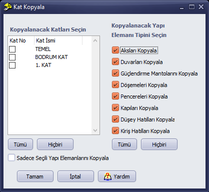
Copy Storey window
Storey Selection
The KatSeç (Select Storey) button on the bottom bar or the View › Select Storey to Show command opens a window in which the storeys are listed as buttons; clicking a storey and pressing OK makes that storey active.
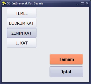
Select Storey to Display window
Automatic Node Editing
Modify › Automatically Fix Nodes or the Automatically Fix Nodes button in the Static Analysis window tries to eliminate model errors by merging nodes that are very close to each other. The editing can be done on all storeys or only on the active storey, on all objects or only on the selected objects; the object types to be edited are selected from the list.
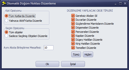
Automatic Node Editing window
Warning: After automatic fixing, check the model, especially the TEMEL storey; if you see an unexpected change, use Undo (Ctrl+Z).
Details: Copy Storey, Multiple Property Change, Multiple Copy and Node Editing.
11. 3D View
The 3D button on the right toolbar opens the 3D view window of the model. When the window is first opened, it reads “Görüntülemek İçin Üzerine Tıklayınız” (Click here to view); when the window is clicked, the model is drawn. The toolbar contains the All Storeys, Selected Only, Beam Finite Elements and Shell Finite Elements options. The model is rotated with the mouse; the window can be enlarged.
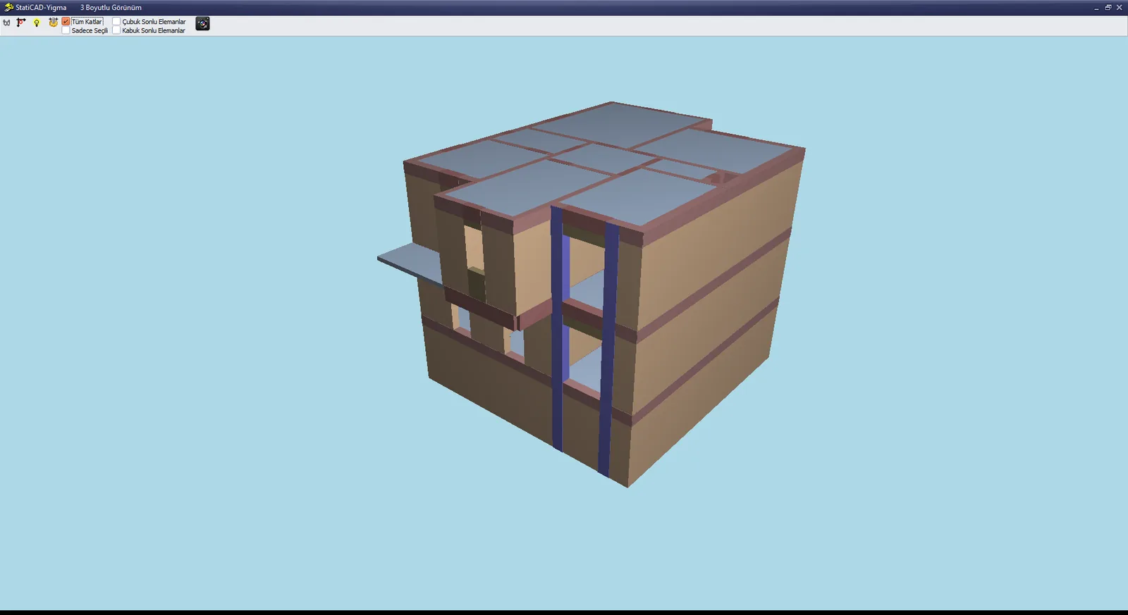
3D View window (sample project)