Starting the Program and the Main Screen
1. Running the Program
- Run the StatiCAD shortcut on the desktop or the program file in the installation folder:
C:\StatiCAD\Ultimatex64\StatiCAD.exefor Ultimate,StatiCAD-Yigma.exefor the Masonry editions andStatiCAD-Betonarme.exefor the Reinforced Concrete edition (see Program Overview). - The splash screen at start-up shows the product name, the version and the “64 Bit” information; “Loading …” texts scroll in the bottom line while the forms are loaded.
- When loading is finished, the start (dock) screen that fills the screen opens (see “Start (Dock) Screen”).
If there is an internet connection and a new version has been released, the Güncelleme Uyarısı (Update Notice) window may appear at start-up. Installing the update is the user’s decision; the program must be closed during installation.
For installation, see the article Installing the 64-Bit Version.
2. Start (Dock) Screen
The start screen is the main window of the program. From here you reach the project file operations, the main working screen, and the analysis and settings windows. The items are presented as large icons; an icon enlarges when the pointer is placed over it.
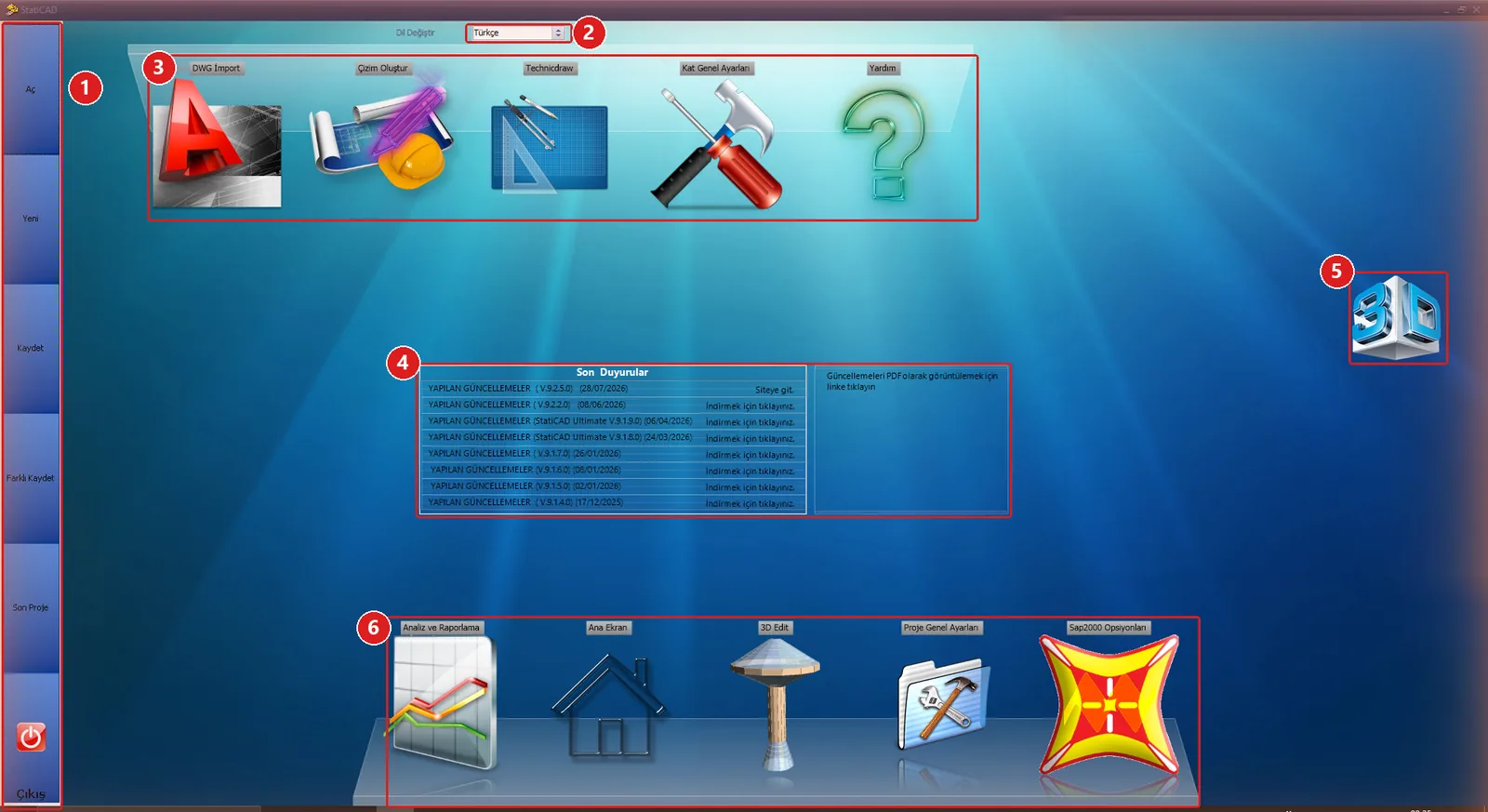
Start (dock) screen
Parts of the start screen
| No | Part | Items and their functions |
|---|---|---|
| 1 | Left rotary menu | Open: project open dialog · New: opens the main screen and sets up an empty project · Save · Save As · Last Project: recovers the project from the last undo record · Exit: closes the program (asks whether to save if the project has changed). |
| 2 | Change Language | List of interface languages. When the language is changed, the program restarts itself. |
| 3 | Top dock | DWG Import: tool for importing architectural DWG/DXF files · Create Drawing: Drawing Selection window · Technicdraw: drawing editor · General Storey Settings · Help: help file and knowledge base. |
| 4 | Latest Announcements | Announcements and release notes read from the internet (left empty if there is no connection). |
| 5 | 3D preview | When clicked, the 3D preview of the open project is shown in a panel sliding in from the right. |
| 6 | Bottom dock | Analysis and Reporting: Static Analysis window · Main Screen: the main working screen · 3D Edit: 3D / finite element editing window · Project General Settings · Sap2000 Options: SAP2000 export options. |
Tip: To start modelling, click the Main Screen icon in the bottom dock. On the main screen, the File › Exit command closes only the main screen and returns to the start screen; to exit the program completely, use the Exit item on the start screen.
3. Opening the Main Screen
- Click the Main Screen icon in the bottom dock.
- The main working screen opens so that it fills the screen. At the first start, a small 3D View window may also appear at the bottom right; it does not interfere with work and can be closed with the close button at its top right corner.
- In an empty project the active storey is shown as BODRUM KAT (basement storey). You can now open a project (see Opening a Project) or draw a new model (see Modelling Tools).
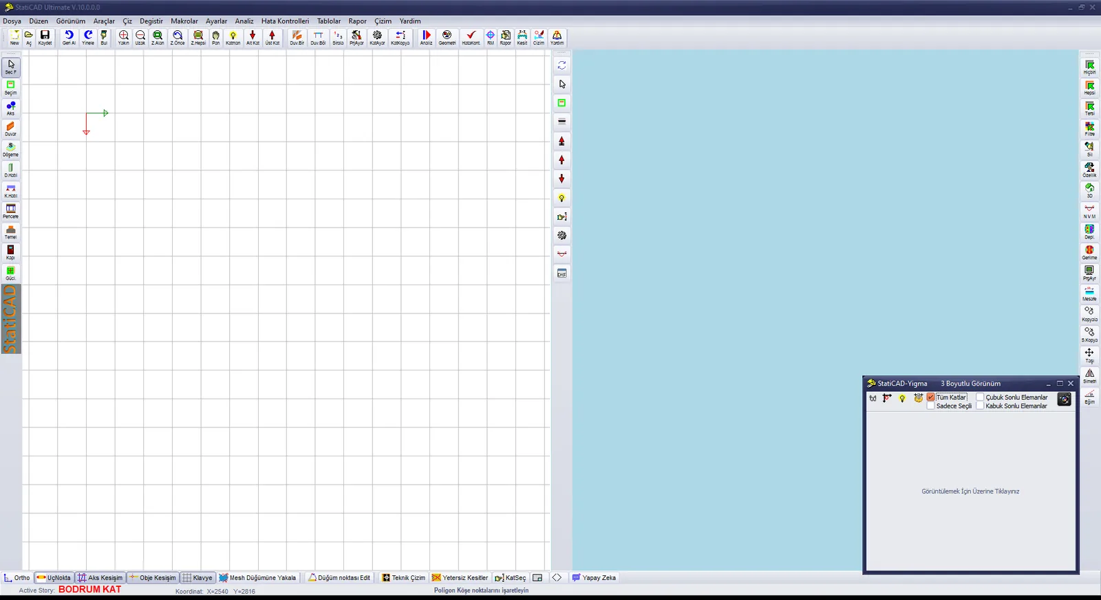
Main working screen – empty project
4. Parts of the Screen
All modelling, analysis, result display and reporting operations are carried out from the main working screen. By default the screen is split: the 2D plan of the active storey is on the left half and the 3D view of the model is on the right half.
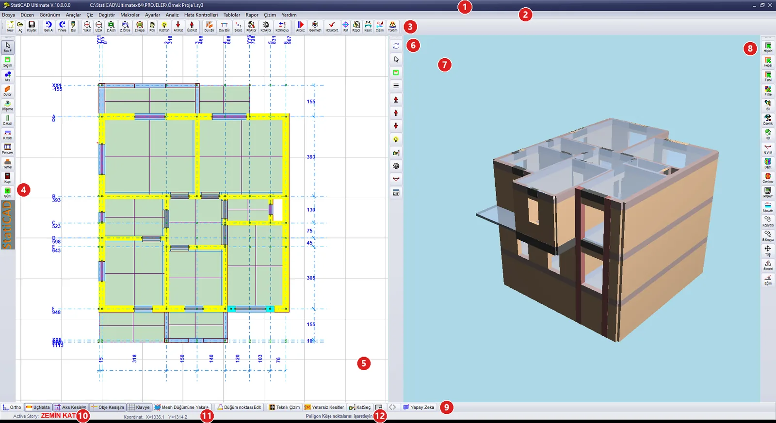
Main working screen (sample project open)
Parts of the main working screen
| No | Part | Description |
|---|---|---|
| 1 | Title bar | Program name and version (StatiCAD Ultimate V.10.0.0.0) and the full path of the open file. |
| 2 | Menu bar | 14 menus: File, Edit, View, Tools, Draw, Modify, Macros, Settings, Analysis, Error Checks, Tables, Report, Drawing, Help (see Menu Bar). |
| 3 | Top toolbar | File, undo, zoom, storey, edit, settings, analysis, report and drawing commands (see Top Toolbar). |
| 4 | Left drawing toolbar | Selection modes and element drawing commands (see Left Drawing Toolbar). |
| 5 | Drawing area | 2D plan of the active storey. Elements are drawn, selected and edited here. |
| 6 | 3D panel toolbar | Refresh, selection, storey and view buttons of the 3D view on the split screen (see 3D Panel Toolbar). |
| 7 | 3D view | 3D view of the model; it can be rotated with the mouse. |
| 8 | Right toolbar | Selection, delete, properties, 3D, result display, copy and move commands (see Right Toolbar). |
| 9 | Bottom toolbar | Snap switches, node editing, technical drawing, insufficient sections, storey selection, split screen, command line and Artificial Intelligence buttons (see Bottom Toolbar and Status Line). |
| 10 | Active storey | The name of the active storey (for example ZEMİN KAT, the ground storey) next to the “Active Story” label. |
| 11 | Coordinates | Position of the pointer in the drawing area (X, Y; cm). |
| 12 | Hint line | The operation expected by the active command (e.g. “Duvarın ilk ve ikinci noktasını işaretleyin” – Mark the first and second points of the wall) or the result of the last operation (e.g. “Data Kaydedildi” – Data Saved). |
Tip: You can follow the current state of the program in three places: the title bar (open file), the active storey label and the hint line (the operation expected by the active command). A button that appears pressed on the left toolbar shows the active drawing mode.