Project, Storey and Program Settings
1. Project General Settings
The Project General Settings window is the main settings window in which the building type, the code, the seismic and soil parameters, the analysis methods, the materials, the load combinations and the design options are defined. It is opened with Settings › Project General Settings (Ctrl+P), the PrjAyar (Project Settings) button on the top bar, the Project General Settings icon on the start screen or the right-click menu on an empty area. Changes are applied with OK and abandoned with Cancel.
The tabs are arranged in two rows; the row containing the selected tab moves to the bottom. The visible tabs vary with the building type and the code: the TBDY2018 tab appears when TBDY 2018 is selected, and the Earthquake tab appears when TDY 2007 is selected.
Tip: You can move between the tabs with Ctrl+Tab after clicking once in the window. After entering a value, close the window with OK.
Code Selection Tab
The building type (Masonry Building, Reinforced Concrete Building, Timber Building, Hybrid), the Earthquake Forces and Design Code selections, the Ductility Level and the This Project Is an Assessment and/or Strengthening Project of an Existing Building box are on this tab. The lower section contains the elements to be included in the finite element model and the Performance B.15 (TBDY 2018) options.
Warning: A new project may inherit some settings, such as the building type, from the project opened last in that session; for example, in a new project opened after a reinforced concrete project, the building type may come up as Reinforced Concrete Building and the element type in the wall window as Reinforced Concrete Shear Wall. Check this tab in every new project.
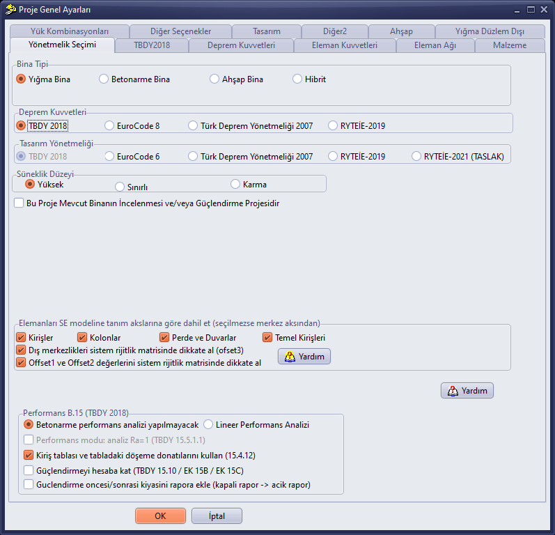
Code Selection tab – new project (Masonry Building, TBDY 2018)
TBDY2018 Tab
When TBDY 2018 is selected, the seismic ground motion level (DD-1 … DD-4), the map spectral acceleration coefficients (SS, S1), the building importance factor (I), the building usage class (BKS), the structural system coefficients (R, D), the soil bearing capacity and modulus of subgrade reaction, the number of rigid basement storeys, the address of the structure and the map coordinates, and the Local Soil Class (ZA … ZF) are entered on this tab. The Spectrum button shows the design spectrum.
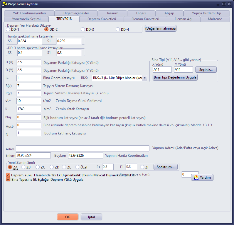
TBDY2018 tab
Warning: Take the SS and S1 values from the AFAD Turkey Earthquake Hazard Map according to the coordinates of the structure. Do not run the analysis without checking the default values.
Other Tabs
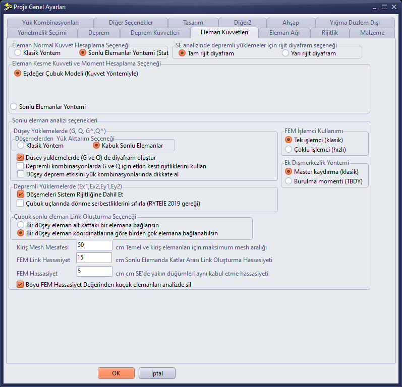
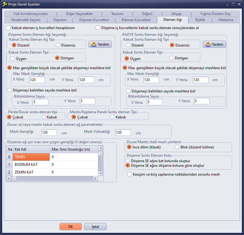
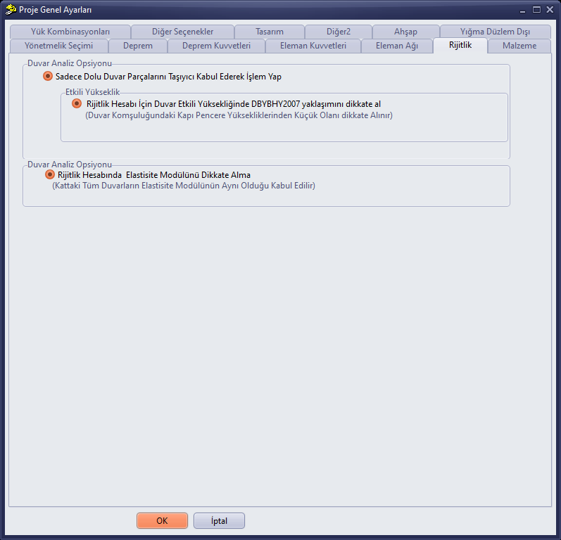
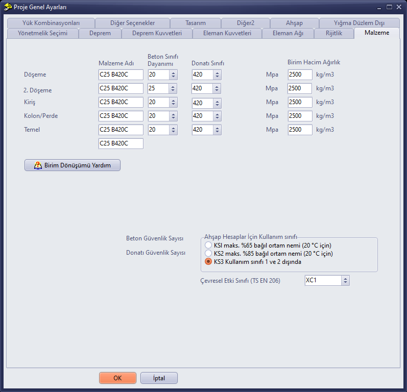
The images below are taken from a masonry sample project prepared with TDY 2007; the contents of the tabs may differ according to the building type and the code.
Tabs of Project General Settings
| Tab | Content |
|---|---|
| Earthquake (TDY 2007) | Effective ground acceleration coefficient, building importance factor, response modification coefficient, spectrum coefficient, soil group and seismic zone. |
| Earthquake Forces | Calculation method of the seismic load acting on the storeys (equivalent seismic load, modal analysis), modal analysis with finite element matrices, number of modes, diaphragm and mass options, Ct coefficient. |
| Element Forces | Calculation methods for element axial force and shear/moment, use of the FEM processor, eccentricity method, link generation and mesh precision. |
| Element Mesh | Mesh type and sizes of the slab and wall/jacket shell element mesh. |
| Stiffness | Wall analysis option, effective height and modulus of elasticity options. |
| Material | Concrete and reinforcement grades, unit weights and exposure class (TS EN 206) for slab, beam, column/shear wall and foundation. |
| Load Combinations | Load factors used in compressive and shear stress checks (e.g. 1.4G+1.6Q and 1.0G+HYKK*Q+1.0E), snow and wind loads, lateral earth pressure. |
| Other Options | Beam–column connection, tie column stiffness, SAP2000 transfer, semi-basement and automatic wall merging options. |
| Design | Design options for columns, beams, foundations and punching shear. |
| Other2 | Beam finite element matrix options, penalty parameters, support generation and analysis type options. |
| Timber | Parameters of timber elements and fire calculation. |
| Masonry Out-of-Plane | Parameters of the out-of-plane check of masonry walls (TS EN 1996-1-1 / EC6 Annex E). |
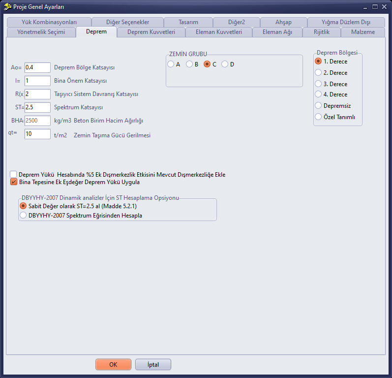
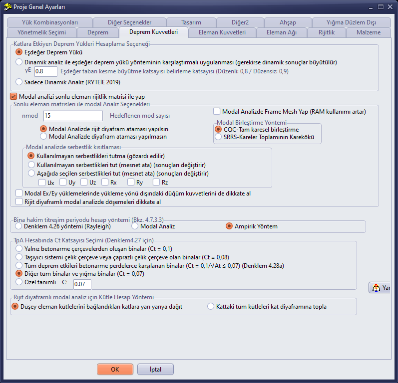
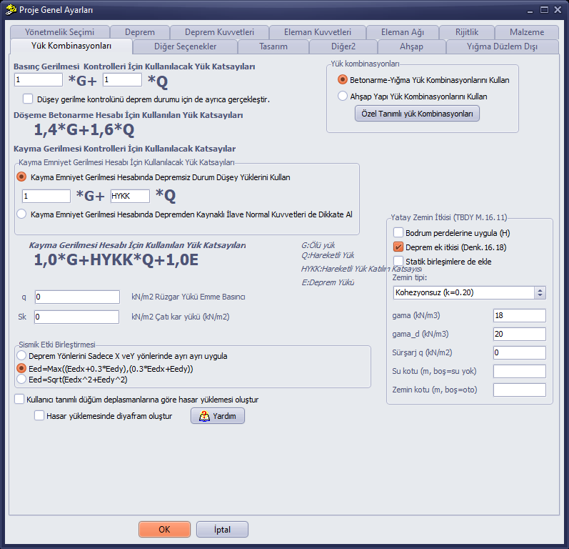
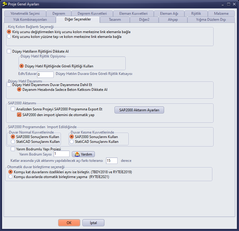
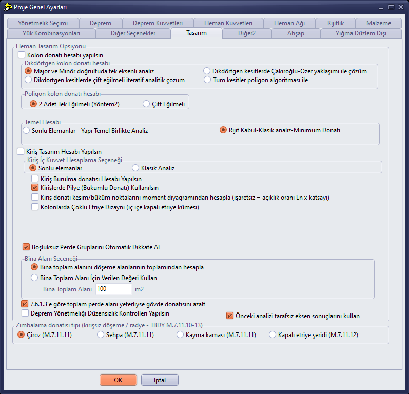
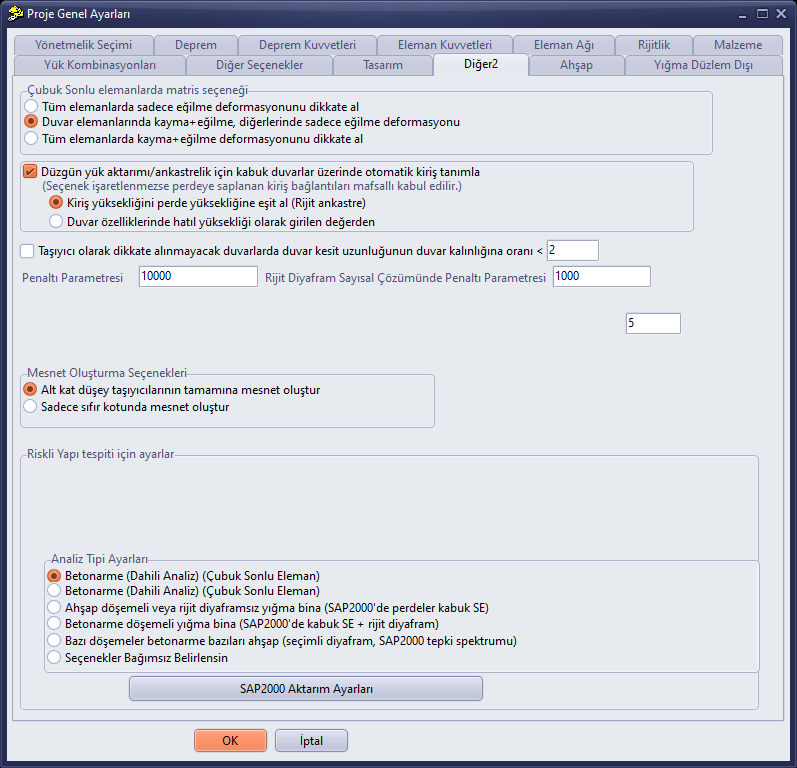
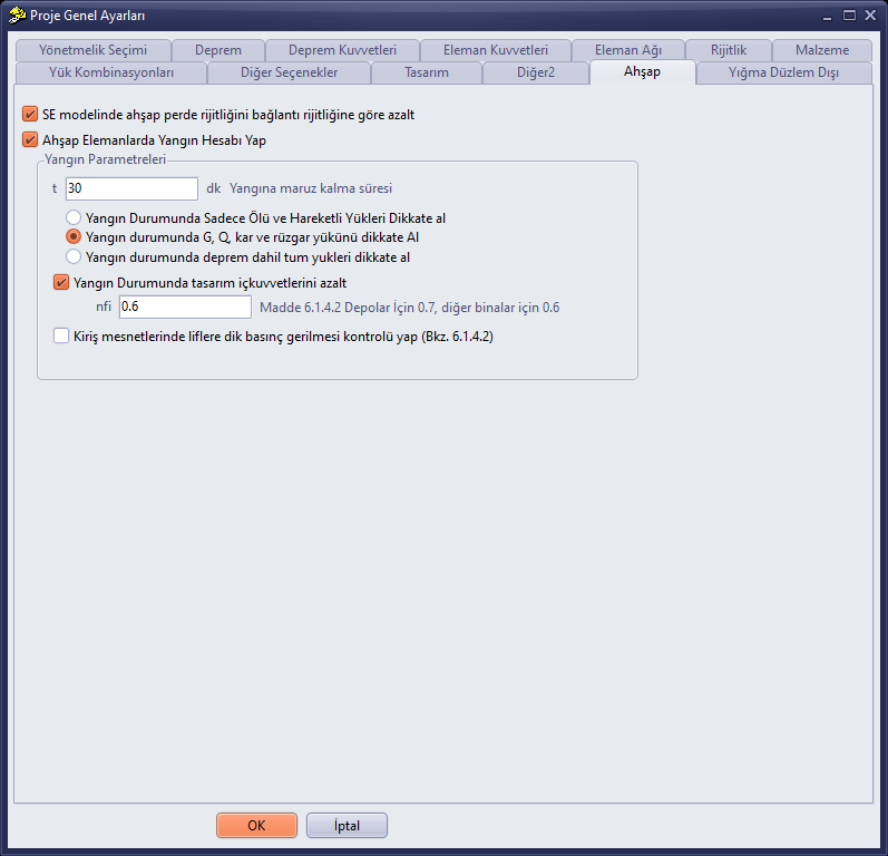
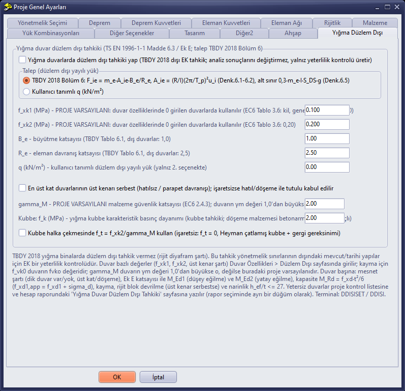
For the seismic parameters: Obtaining the TBDY 2018 seismic parameters (SS, S1).
2. General Storey Settings
Settings › General Storey Settings (Ctrl+G) is opened with the General Storey Settings icon on the start screen or the right-click menu on an empty area. The window contains the Project Name, Project Author and the storey table. The table columns are: Storey No, Output Index (the short name used in reports and drawings), Storey Name, Storey Height, Building Height and HYKK (live load participation factor). Storeys are added or deleted with the Add Storey and Delete Storey buttons; the height of new storeys is taken from the Default Storey Height box. The window is modal; it must be closed with OK or Cancel.
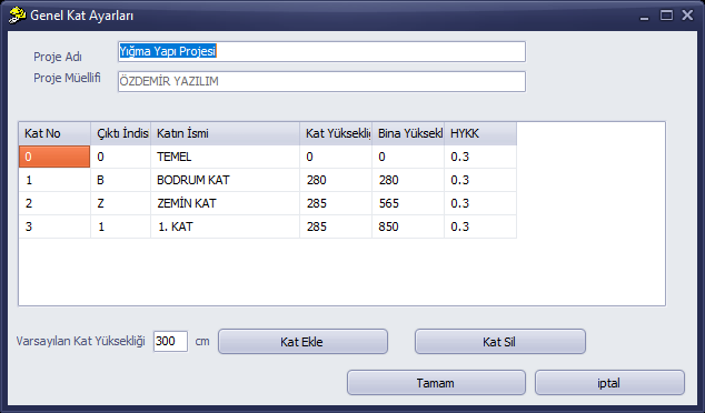
General Storey Settings window
Details: General Storey Settings.
3. Window for Adding and Deleting Storeys
The KatAyar (Storey Settings) button on the top bar or the Settings › Storey Settings command opens a second window in which storeys are added and deleted according to their position. The title of this window is also General Storey Settings; it is distinguished by the buttons at the bottom: the Add Storey at Bottom, Insert Storey, Add Storey at Top, Delete Bottom Storey, Delete Selected Storey and Delete Top Storey buttons, the Automatic Storey Name box and the Storey Height field.
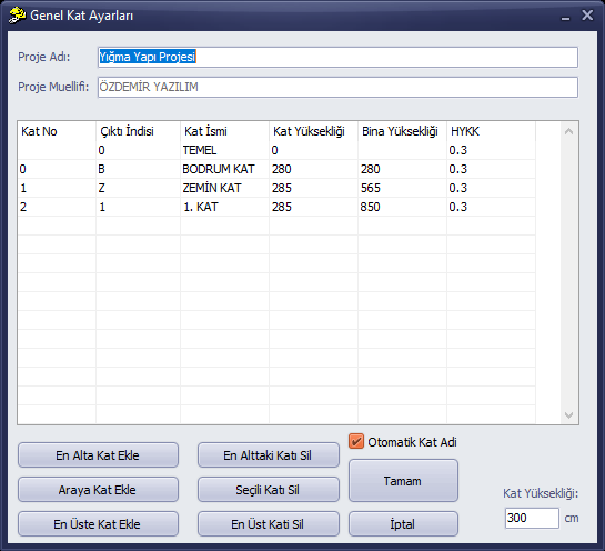
Window for adding and deleting storeys
4. Program Settings
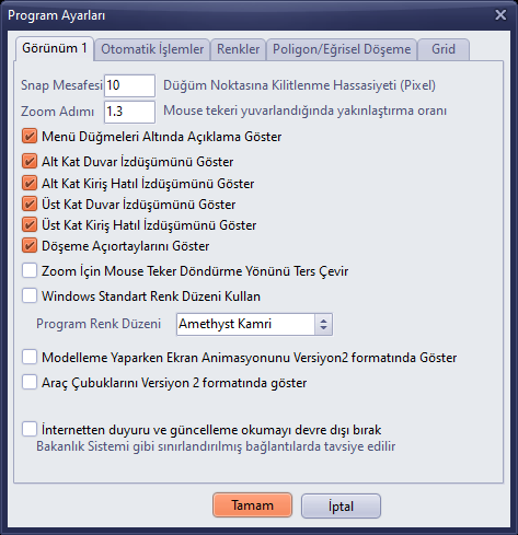
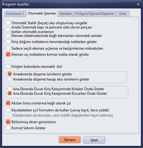
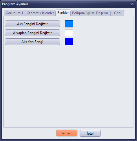
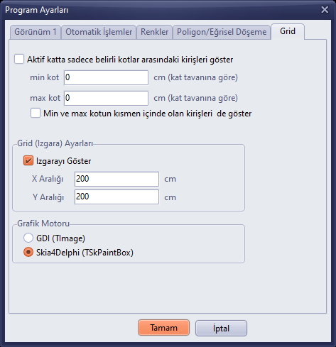
Program Settings are user-specific settings that are independent of the project. They are opened with the PrgAyr (Program Settings) button on the right toolbar or with Settings › Program Settings. There are five tabs:
| Tab | Main options |
|---|---|
| View 1 | Snap Distance (pixels), Zoom Step, projection and annotation displays, Show toolbars in Version 2 format, Disable reading announcements and updates from the internet. |
| Automatic Operations | Automatic grid line and element operations, wall pieces above doors/windows, Split screen view, Show Command Line. |
| Colours | Grid line, background and grid line text colours. |
| Polygon/Curved Slab | Display options for nodes (joints) and mesh before and after analysis. |
| Grid | Grid spacings (X, Y), elevation interval filter and Graphics Engine (GDI or Skia4Delphi). |

Grid
5. Layer Settings
The Layer Settings window (Ctrl+L or Katman (Layer) on the top bar) determines which element groups are visible in the drawing area: grid lines, element grid lines, walls and strengthening in the X and Y directions, slabs, slab calculation axes, beams and tie columns, doors and windows, foundations, and element name and dimension texts. The Make All Layers Visible and Make All Layers Invisible buttons provide bulk operations.
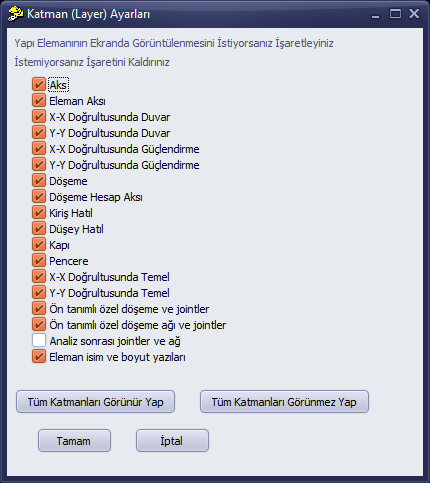
Layer Settings window
Tip: If an element is not visible on the screen, first check the layer settings and the active storey; then fit the whole model on the screen with Z.Hepsi (Zoom All).