Results and Tables
1. Displaying Finite Element Results
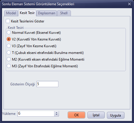
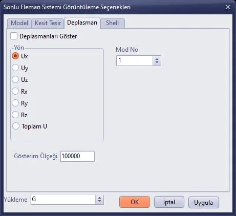
The N V M and Gerilme (Stress) buttons on the right toolbar open the Finite Element System Display Options window and switch the 3D panel on the split screen to the finite element model. The window has four tabs: Model (elements and labels to be shown), Section Forces (N, V2, V3, T, M2, M3), Displacement (Ux, Uy, Uz, Rx, Ry, Rz, total U) and Shell (shell forces and stresses, colour scheme). The loading case (G, Q, EX1, EX2, EY1, EY2, Damage, G^ …) is selected from the Loading list at the bottom; Apply updates the display. For this feature, the analysis must have been run and the results must be in memory.
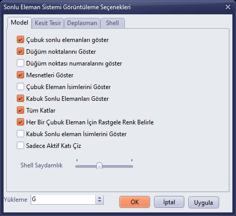
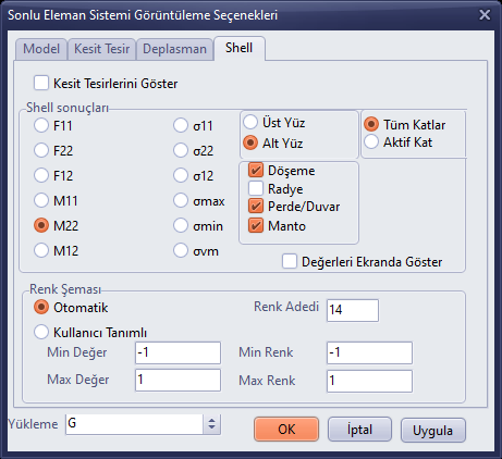
- Click the N V M or Gerilme (Stress) button.
- On the relevant tab, tick the Show Section Forces / Show Displacements box and select the component.
- Select the loading case from the Loading list and the scale from the Display Scale box.
- Click Apply; the 3D panel will be updated. Close the window with OK or Cancel.
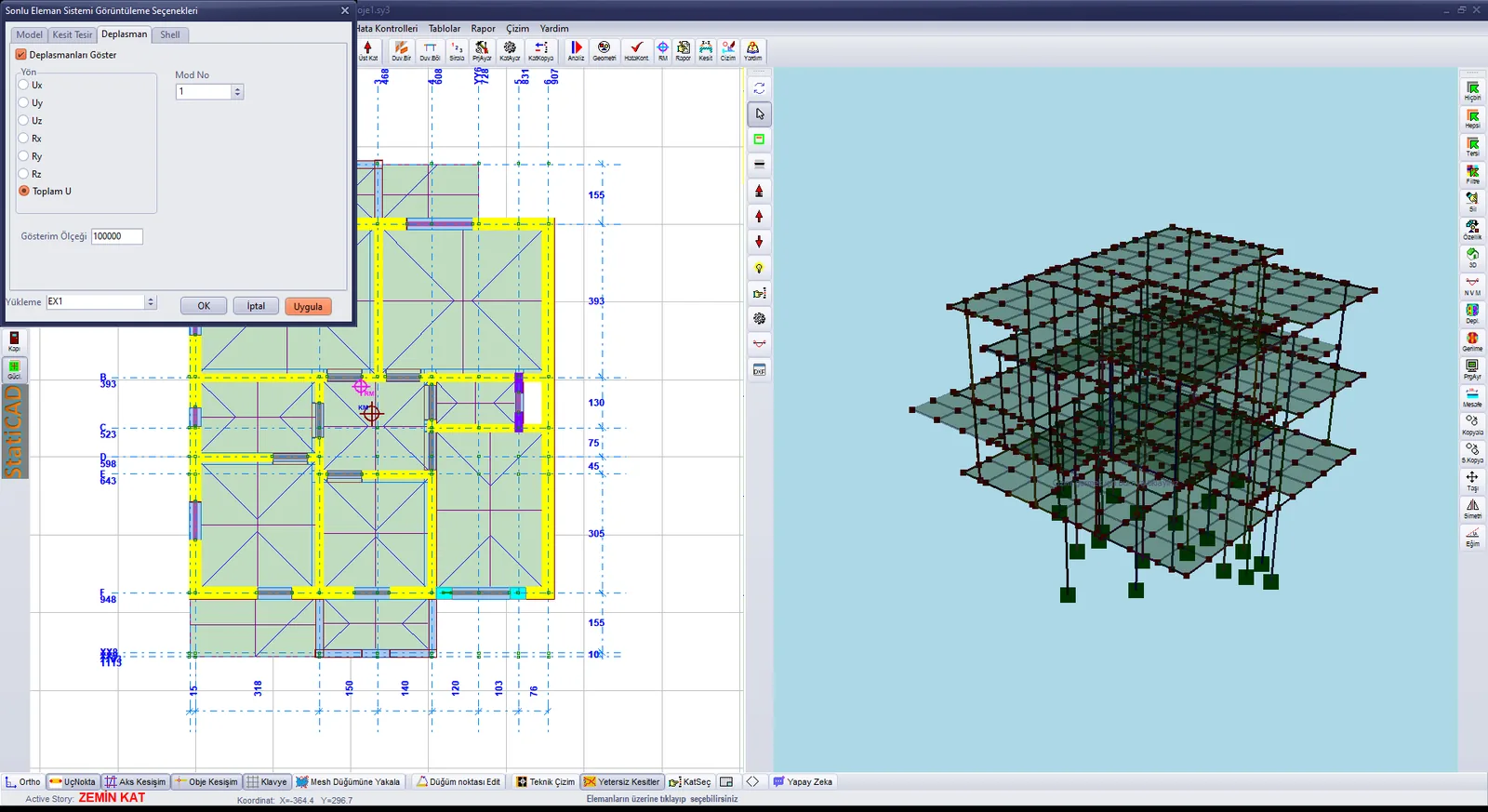
Displacement view under the EX1 loading: the options window and the finite element model in the 3D panel
2. Reinforcement and Result Tables
The Tables menu contains the slab, column, beam, wall (shear wall) and continuous foundation reinforcement tables, the reinforcement selection and the modal analysis results. In the tables, multiple selection can be made with Shift or Ctrl; the All Storeys box and the << / >> buttons allow navigation between storeys. Reinforcement changes made in the tables are saved with OK.
Slab Reinforcement
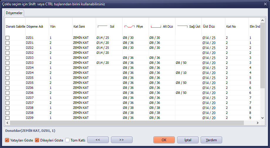
Tables › Slab: slab reinforcement table
Column Reinforcement
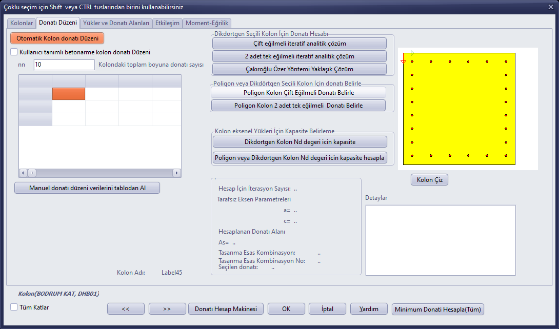
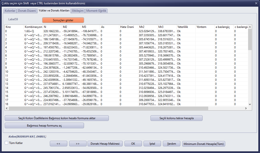
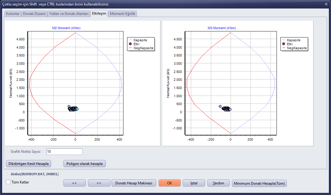
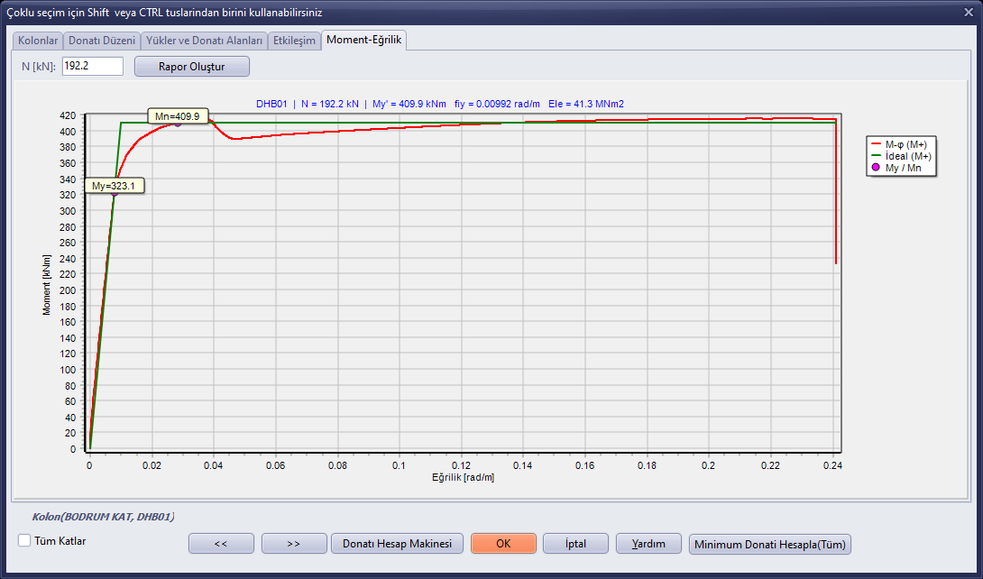
The column table has five tabs: Columns (list of sections and reinforcement), Reinforcement Layout (section and reinforcement arrangement of the selected column), Loads and Reinforcement Areas, Interaction (N-M interaction diagrams) and Moment-Curvature. The Reinforcement Calculator and Calculate Minimum Reinforcement (All) buttons are also in this window.
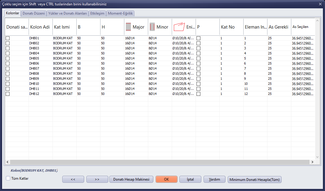
Tables › Column: Columns tab
Beam Reinforcement
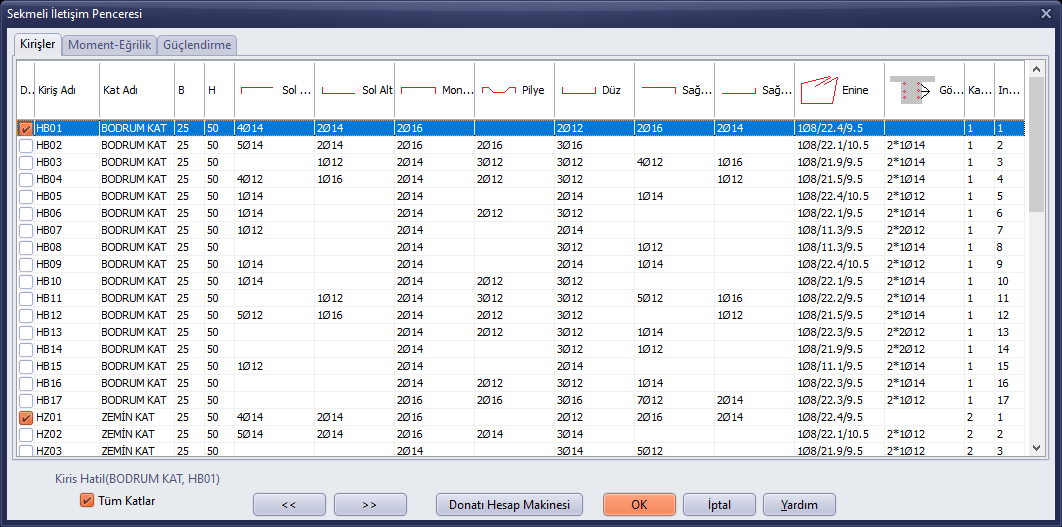
Tables › Beam: beam reinforcement table (Beams, Moment-Curvature, Strengthening tabs)
Tables › Wall Reinforcement lists the shear wall reinforcement (Shear Walls, Interaction, Shear Wall Group, Moment-Curvature, Strengthening tabs; Export to Excel), and Tables › Continuous Foundation lists the reinforced concrete continuous foundation reinforcement. In masonry buildings these tables may be empty.
3. Modal Analysis Results
- Run the Tables › Modal Analysis with Finite Elements command.
- Select a table from the Select Table list: Periods and Frequencies, Effective Modal Mass, Mass Participation Ratios, Modal Participation Ratios, Base Shear and Modal Effective Mass, Nodal Forces, Combined Nodal Forces, Combined Base Shear.
- Click View Selected Table; the table will be listed in the window. Export to Excel exports the table to Excel.
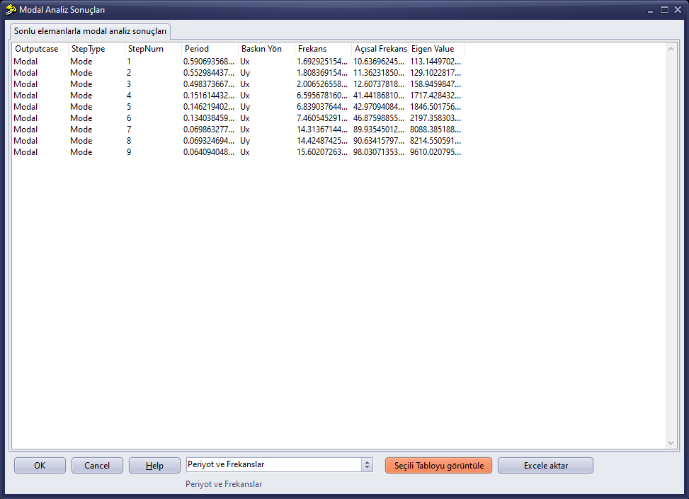
Modal Analysis Results: Periods and Frequencies table