End-to-End Example: A Simple Masonry Building
In this example, a simple building measuring 6.00 × 4.50 m, with a single storey, 24 cm masonry walls, one door and one window, is modelled from scratch, analysed and saved. The example shows how the tools described in the other articles of the guide are used together, and it is a reliable workflow example for AI agents. All dimensions are in cm.
1. New Project and Code
- On the main working screen, create a new project with Ctrl+N. The active storey becomes BODRUM KAT (basement storey).
- Open Project General Settings with Ctrl+P. On the Code Selection tab, select Masonry Building; verify that TBDY 2018 is selected as Earthquake Forces (see Project, Storey and Program Settings).
- On the TBDY2018 tab, enter the seismic ground motion level, the SS and S1 coefficients, the building importance factor and the local soil class according to the project (see Project, Storey and Program Settings).
- Close the window with OK.
2. Drawing the Walls with the Command Line
- Open the command line by clicking the command line icon on the bottom bar.
- Click the input box, type
wand press Enter. - In the Wall Properties dialog, select Masonry Wall as the Element Type, check that the Wall Width is 24, and click OK.
- Type the following coordinates into the input box one after another, pressing Enter after each:
0,0·600,0·600,450·0,450·0,0 - Finish the command by right-clicking in the drawing area; then fit the model on the screen with Z.Hepsi (Zoom All).
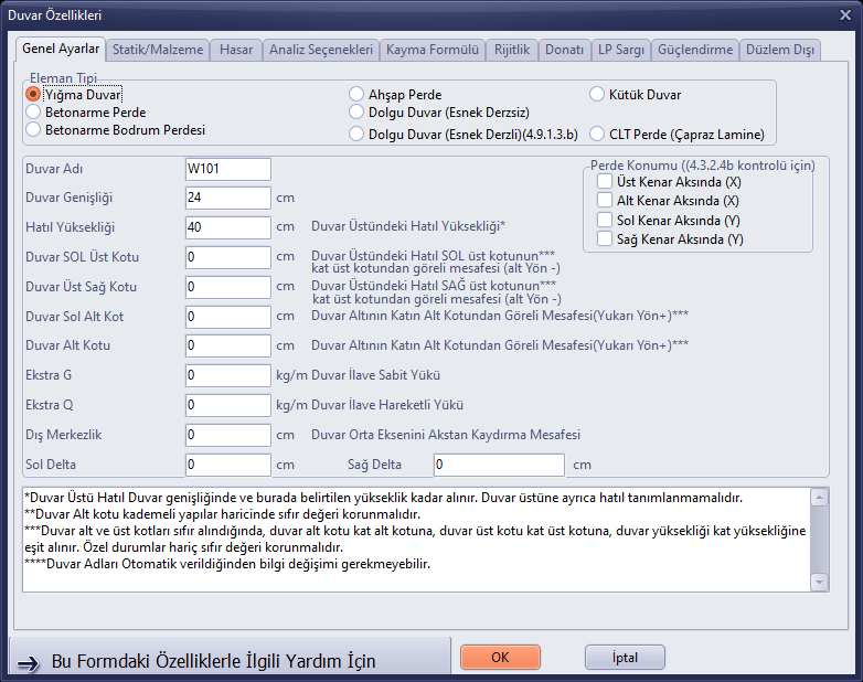
Wall Properties: Masonry Wall, 24 cm

Four walls drawn with the command line; the coordinates entered in the history box
Tip: If a different element type was used in the previous project, the window may open with that type (for example Reinforced Concrete Shear Wall); check the element type before pressing OK. Since the Y axis points downward on the screen, the value 450 gives the lower edge of the room.
3. Slab
- Click the Slab button on the left toolbar; the Slab Drawing tool window opens.
- Click the upper left corner (0,0) and the lower right corner (600,450) of the room. Since snapping is on, the clicks snap to the wall corners.
- The slab (SB01) is created and appears in the 3D panel. Finish the command by right-clicking.
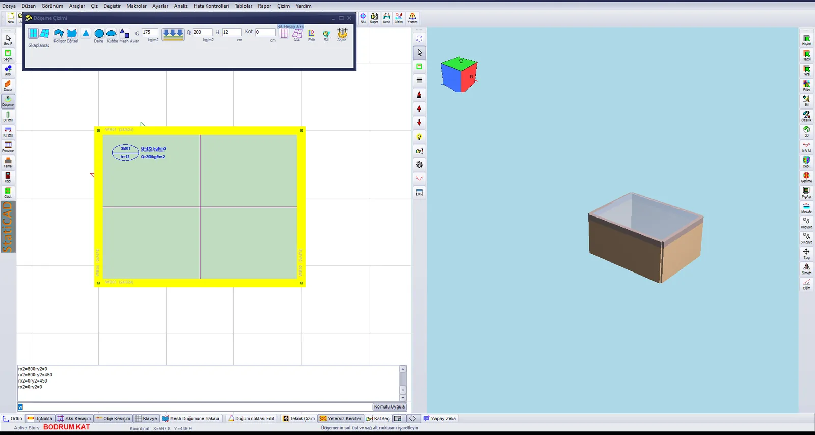
Plan and 3D view after the slab is added
4. Door and Window
- Click the Door button. Click the left end of the lower wall (0,450), then click any point to the right on the same wall. The door is placed 150 cm away from the left corner. Right-click.
- Click the Window button. Click the left end of the upper wall (0,0), then click a point to the right on the same wall. The window is placed. Right-click.
- Check the openings by pressing Refresh in the 3D panel.
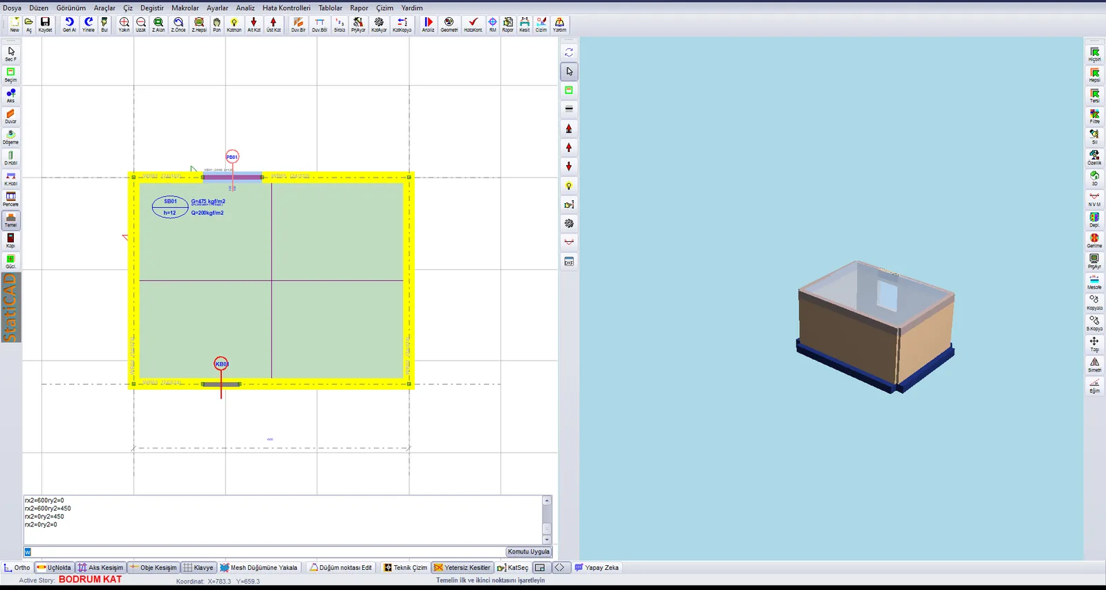
Storey plan with the door and window added; the window opening in the 3D view
5. Grid Lines and Foundations
- Run the Modify › Create Grid Line If Missing command; grid lines are created under the walls.
- Go to the TEMEL storey with Ctrl+Down Arrow.
- Click the Foundation button, and with Masonry Wall Foundation selected in the Foundation Properties dialog, click OK.
- Draw the four foundations with two clicks each: (0,0)–(600,0), (600,450)–(0,450), (600,0)–(600,450), (0,0)–(0,450). The corner nodes are shown with green dots.
- Finish the command by right-clicking and return to BODRUM KAT with Ctrl+Up Arrow.
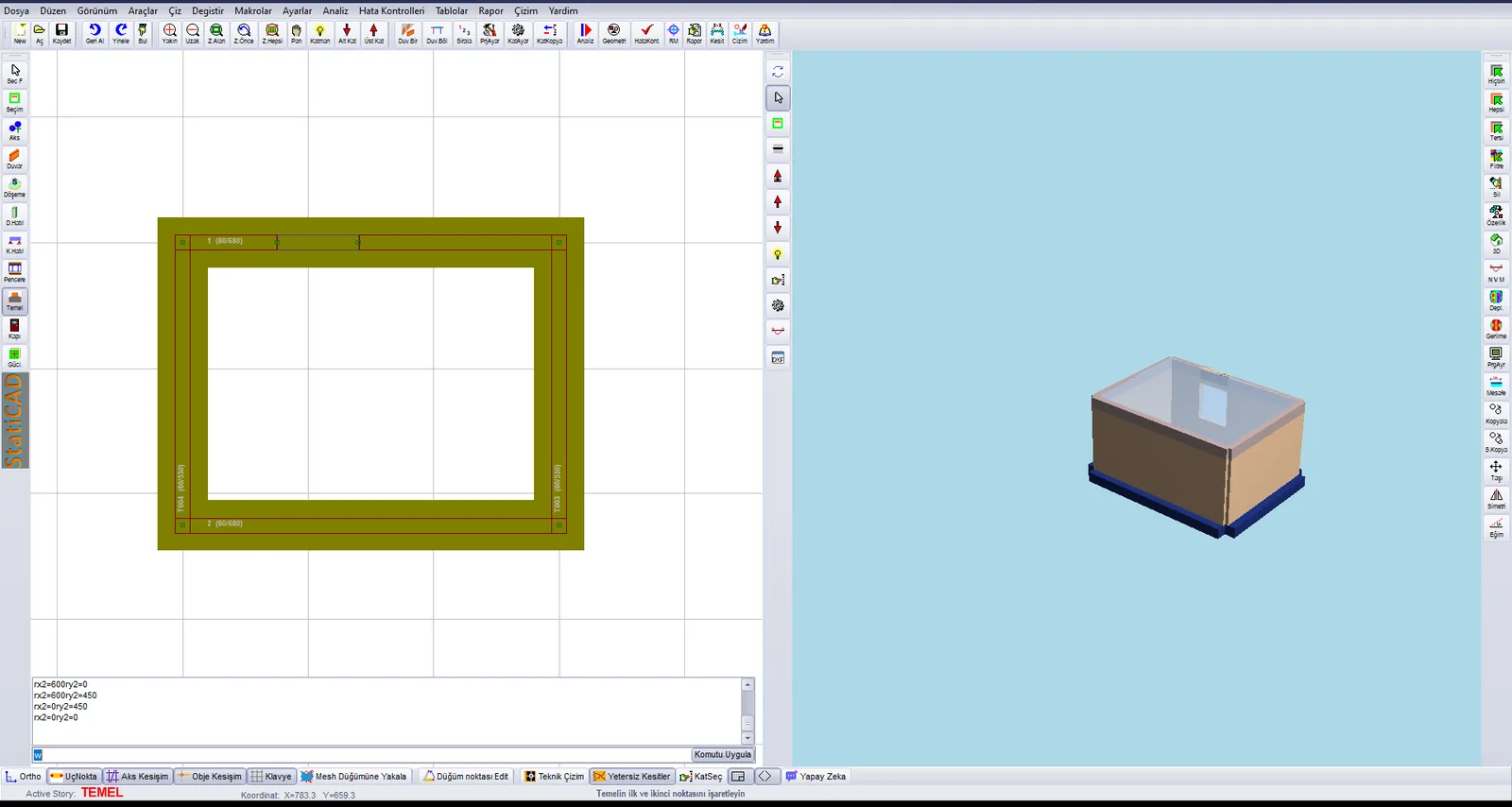
The four masonry wall foundations drawn on the TEMEL storey
6. Analysis
- Click the Analiz (Analysis) button on the top bar and press Start Analysis.
- Wait for the “Analiz Tamamlandı” (Analysis Completed) line in the log (about 3 seconds in this example).
- Examine the warning list; the Help button of each warning opens the relevant knowledge base article.
- Close the window with OK and examine the coloured elements on the plan.
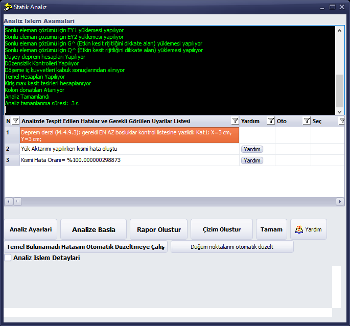
Analysis result and warnings of the example building
In this example the walls appear in purple, that is, insufficient in terms of shear stress. In such a case, the wall thickness can be increased, walls can be added, tie columns can be used or the design can be changed to reinforced walls; after the change, the analysis is repeated. Engineering decisions are the responsibility of the responsible engineer of the project.
7. Saving
- Open the Save As dialog with Ctrl+Alt+S.
- Click the File name box, press Ctrl+A and type the full path (for example
C:\Projeler\OrnekYigma1.sbd); press Enter. - Verify that the file path appears in the title bar and Data Kaydedildi (Data Saved) appears in the hint line. A .sy4 copy is also created in the folder next to the .sbd file.
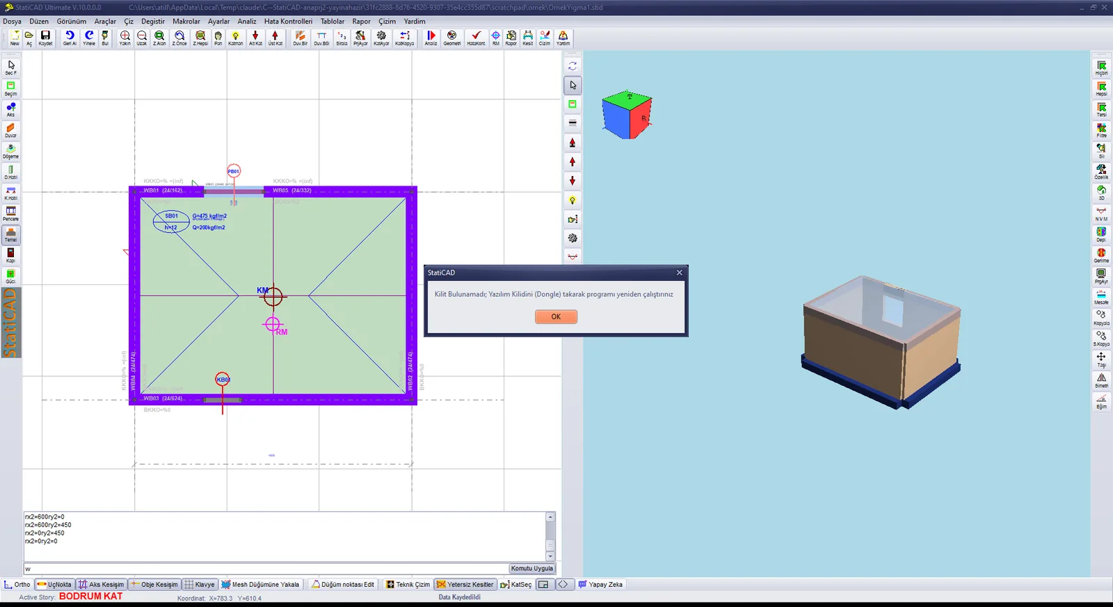
File path in the title bar after saving and “Data Kaydedildi” in the hint line
Next steps: for the calculation report, go to Reporting; for project drawings, go to Drawing (Sheet) Production.