DXF Underlay: Modelling over an Architectural or Formwork Plan
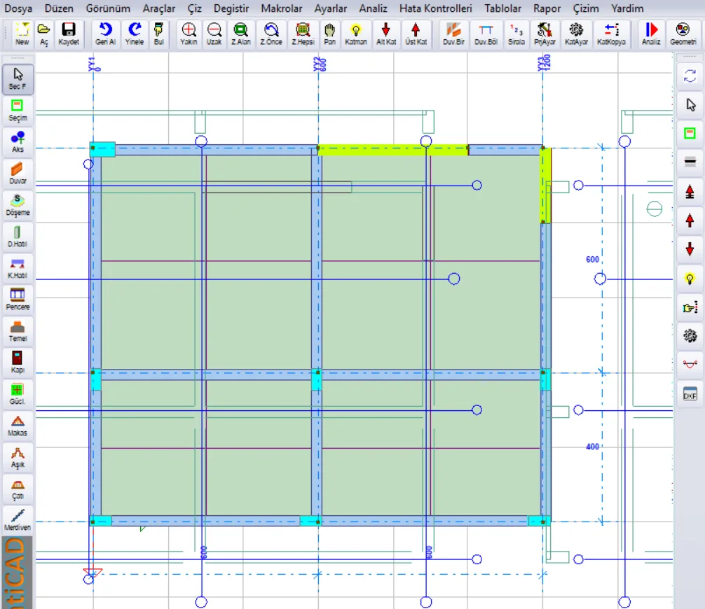
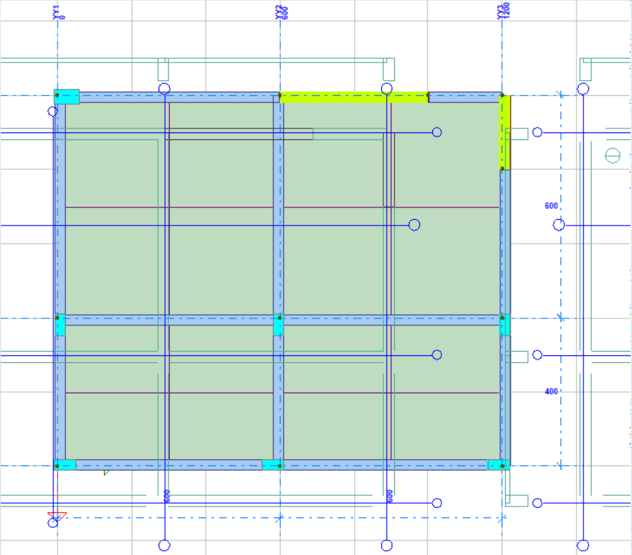
Figure 1 – A formwork plan DXF loaded as an underlay; axis, bond beam and wall lines are visible above the model
1. About this article
The DXF underlay places an architectural plan or formwork plan prepared in AutoCAD or another drawing program behind the modelling screen as a scaled line drawing. You enter the axes, walls, columns and beams over the underlay by snapping to the endpoints of the underlay lines. It serves the same purpose as the background image (a scanned sheet, JPG/PNG); the difference is that a DXF is vector: it does not degrade when zoomed in, its scale is exact and line endpoints can be snapped to.
- The underlay is only a drawing aid; it does not enter the analysis, the calculation or the reports.
- The underlay is saved with the project; when you move the project file to another computer, the DXF file is not needed.
- Each storey can have its own underlay (ground floor architecture, typical floor architecture, formwork plan…).
- The feature is available in all versions of the program.
Information: In the examples in this article, the file altlik.dxf (4668 lines/arcs/circles, 9 layers), which gathers the formwork plans of four storeys and the reinforcement tables on a single sheet, was used together with a small reinforced concrete model with two axes.
2. Quick start
- Switch to the storey where you will put the underlay.
- Give the File → Load DXF Underlay... command (or right-click on an empty place on the modelling screen and select DXF Underlay (architectural / formwork plan)...).
- Select the DXF file with the ... button. The number of objects and the drawing limits appear in the information line.
- Check the Drawing unit: mm if the drawing is in millimetres, cm if in centimetres, m if in metres.
- Untick the layers you do not need (reinforcement, table, dimension…).
- Press Load. The underlay is fitted to the screen.
- If the underlay does not coincide with the model, fit it with Move (two points): first click an axis intersection on the underlay, then the place where that point should be in the model.
- Close the window and start modelling over the underlay. When you save the project, the underlay is saved too.
3. Opening the window
The DXF Underlay window opens from two places; both bring up the same window:
- File menu → Load DXF Underlay... (right below the Load Background Image line).
- In the modelling screen right-click on an empty area → DXF Underlay (architectural / formwork plan)... The Show DXF Underlay line in the same menu hides or restores the underlay without opening the window.
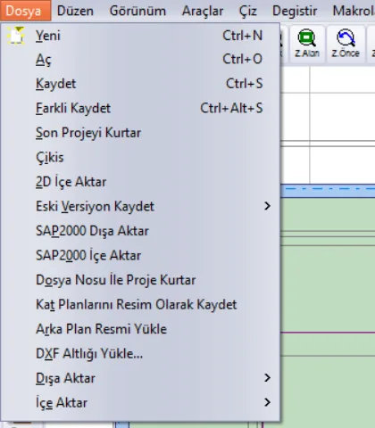
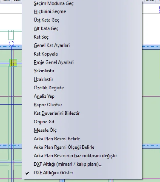
Tip: The lines in the right-click menu appear only when you click on an empty area. If you right-click on a wall, a slab or an axis, the menu of that member opens.
The window is modeless: while it is open you can zoom in and out on the modelling screen, click two points and keep working.
4. The DXF Underlay window
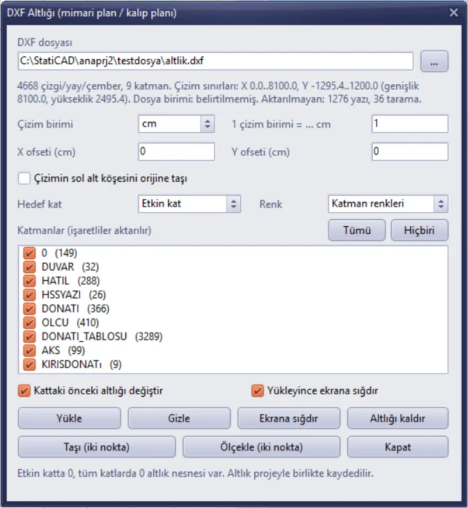
Figure 4 – The DXF Underlay window; a file selected, not yet loaded
4.1. File and information line
The ... button lets you select the DXF file. When the file is read, the information line gives the following:
- the number of lines/arcs/circles that can be imported and the number of layers,
- the drawing limits (X and Y range, width, height) – in the drawing unit,
- the unit recorded in the file (if any),
- the number of texts and hatches that are not imported (see Section 8).
The drawing limits are the quickest way to estimate the scale: for the plan of a building 12 m wide, if the width appears as 1200 the drawing is in centimetres, if 12000 in millimetres, if 12 in metres.
4.2. Drawing unit and scale
The StatiCAD model works in centimetres. You select the unit in which the DXF was drawn from the Drawing unit box; the 1 drawing unit = ... cm box next to it fills in accordingly:
| Drawing unit | 1 drawing unit = ... cm | Typical use |
|---|---|---|
| mm | 0.1 | Formwork and detail sheets |
| cm | 1 | Most architectural plans |
| m | 100 | Site plan, map underlays |
| inch | 2.54 | Projects drawn in inches |
| ft | 30.48 | Projects drawn in feet |
If the unit is recorded in the file, the box comes up accordingly; if it is not recorded (“File unit: not specified” in the information line), cm is assumed and you need to check it. If the drawing was drawn reduced at a scale such as 1/50, you can type the multiplier by hand in the scale box (e.g. 50 for a sheet drawn at 1/50 scale in centimetres).
Tip: If you are not sure of the scale, load the underlay, then use Scale (two points), click an axis span whose length you know and type the real length (see Section 5.2).
4.3. Position: offset and move to origin
By default the origin of the DXF sits at the origin of the model; that is, the point that is (0,0) in the drawing is also (0,0) in the model.
- X offset / Y offset (cm): shifts the underlay by this amount when loading. Y is positive upwards.
- Move the lower left corner of the drawing to the origin: tick this if the drawing was drawn very far from the coordinate system (e.g. in national coordinates); the lower left corner of the drawing is brought to the (0,0) point of the model, and the offsets are added on top of this.
For exact fitting, the most practical way is often to use Move (two points) after loading the underlay (see Section 5.1).
4.4. Target storey
- Active storey: the underlay is loaded only to the storey you are currently working on (default).
- All storeys: the same underlay is copied to each storey separately. Use it if a single plan showing the axis system will be useful on all storeys.
The target storey selection also determines the scope of the Remove underlay, Move and Scale buttons.
4.5. Layers and colour
The list shows the layers in the DXF and the number of objects in each. Only ticked layers are imported. Layers that are off or frozen in the DXF come up unticked. The All and None buttons turn all ticks on or off.
For a structural model, the axis, wall, column and beam layers are usually enough. Switching off the reinforcement, table, furniture and dimension layers both simplifies the screen and keeps the project file small.
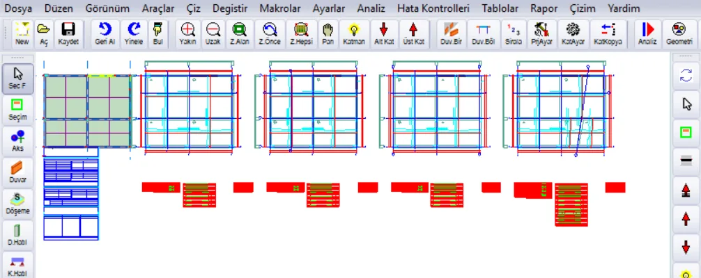
Figure 5 – The sheet loaded with all layers ticked: four formwork plans and reinforcement tables (the model is the green one on the left)
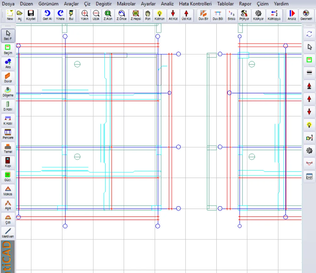
Figure 6 – Zooming in on the same underlay: lines, axis bubbles and circles in layer colours
The Colour box has two options:
- Layer colours: each line takes the layer (or object) colour in the DXF.
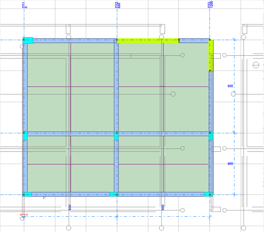
- Single colour (grey): the whole underlay is drawn grey. It is often the most comfortable option so that it does not get mixed up with the colours of the model members.
4.6. Buttons
| Control | What it does |
|---|---|
| Replace the previous underlay on the storey | When ticked (default), a new load deletes the old underlay on the target storey. If you untick it, the new drawing is added over the old one; this way you can put several DXFs (e.g. architectural + formwork) on the same storey. |
| Fit to screen after loading | After loading, adjusts the view to show the whole underlay. |
| Load | Imports the selected file to the target storey with the window settings. If no file is selected, it first asks for the file. |
| Hide / Show | Removes the underlay from the screen or brings it back without deleting it. |
| Fit to screen | Brings the whole underlay on the active storey onto the screen. |
| Remove underlay | After confirmation, deletes the underlay on the target storey (or on all storeys if “All storeys” is selected). |
| Move (two points) | Shifts the underlay by the difference between the two clicked points (see Section 5.1). |
| Scale (two points) | Scales the underlay so that the length between the two clicked points becomes the real length you type (see Section 5.2). |
| Close | Closes the window; the underlay stays in place. |
The line at the bottom of the window shows how many underlay objects there are on the active storey and on all storeys.
5. Fitting the underlay to the model
If you are starting a new project, it is enough to load the underlay and enter the axes directly over it. If you are adding an underlay to an existing model, or if several plans are drawn side by side on the sheet, you need to align the underlay with the model.
5.1. Moving by two points
- Press Move (two points) in the window. The message “first click the reference point on the underlay, then the target point in the model” appears at the bottom of the screen.
- Click a point you know on the underlay (e.g. the A–1 axis intersection or a column corner). The cursor snaps to a nearby line endpoint and the point is marked with a yellow square.
- Click in the model the place where that point should be (e.g. the A–1 axis intersection of the model, or the origin).
The underlay is shifted so that the first point coincides with the second point. If the target storey is “All storeys”, the operation is applied to the underlay on all storeys.
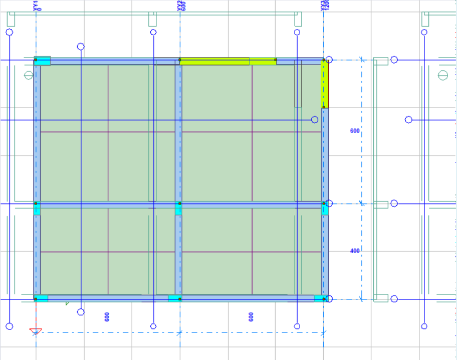
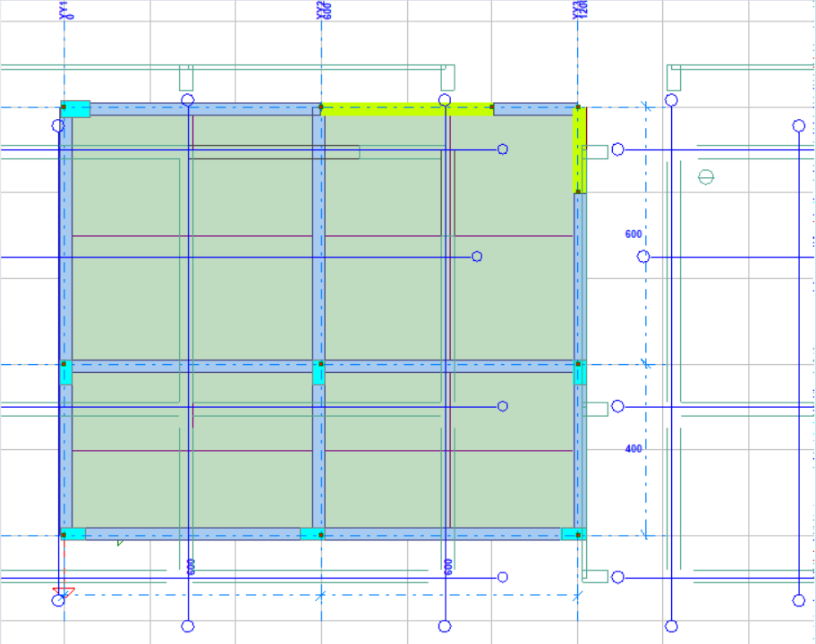
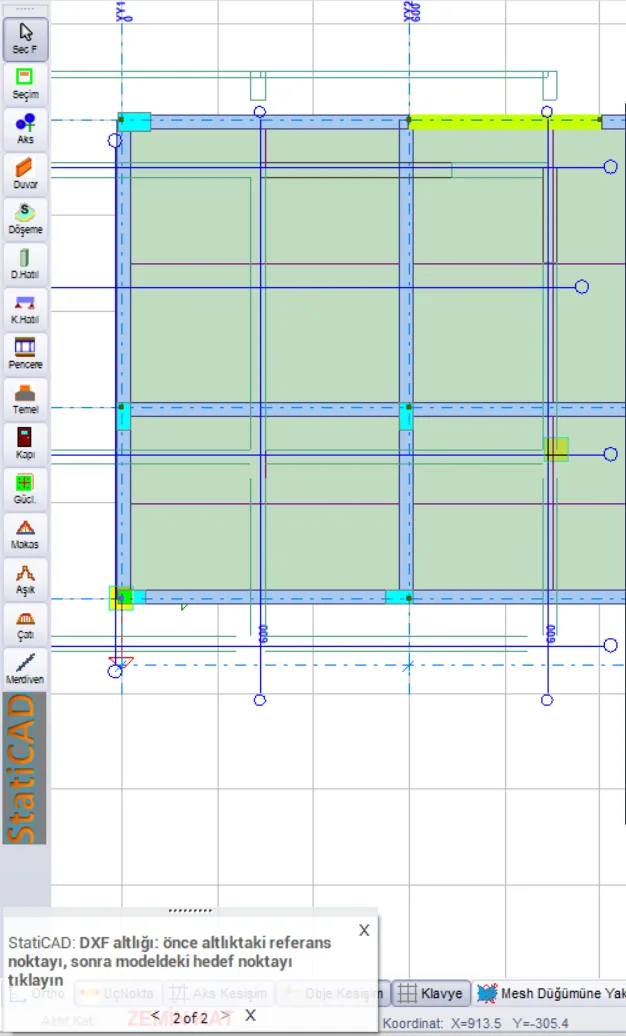
Figure 11 – During Move (two points): the snapped underlay endpoint is marked with a yellow square, the guidance message is at the bottom left
Tip: If several storey plans stand side by side on the sheet, you can load the same DXF for each storey and pull the plan of that storey over the model this way. The other plans stay off screen and do not affect your work; if you do not want that, split the DXF into storeys in the drawing program and load them separately.
5.2. Scaling by two points
- Press Scale (two points) in the window.
- Click two points on the underlay whose real length you know (e.g. between two axes, a wall length with a written dimension).
- In the box that opens, type the real length between these two points in centimetres (the currently measured length is already in the box).
The underlay is enlarged or reduced so that the first point you clicked stays fixed. After the scale is corrected, fit it into place with Move (two points) if necessary.
Caution: The scaling ratio is calculated from the two points you click. Choose the points as far apart as possible and click by snapping to line endpoints; when a ratio taken from a short length is spread over the whole plan, the error grows.
6. Modelling over the underlay
- The underlay is drawn on top of the model; slab and beam fills do not cover the underlay lines.
- Underlay lines cannot be selected: clicking, window selection and Select All do not pick up the underlay. This way you do not touch the underlay by mistake when deleting, moving or copying model members.
- Zooming, panning and scrolling move the underlay together with the model, at the same scale.
6.1. Snapping to endpoints
The endpoints of lines and arcs and the centres of circles on the underlay are added to the model's own snap points. When you draw an axis, wall, column or beam and bring the cursor close to a corner on the underlay, the point is marked with a yellow square and the click lands exactly on that point (Figure 11). Snapping works together with the snap modes in the program's bottom bar (Endpoint, Axis Intersection…).
Information: When the markers showing snap points are on, if there are more than 300 underlay points on the screen, the underlay markers are not drawn (so the screen does not fill up); snapping still works, and the markers appear as you zoom in. When the underlay is hidden, its endpoints are not snapped either.
6.2. Showing, hiding, removing
- Hide / Show (window) or Show DXF Underlay in the right-click menu: the underlay is not deleted, only not drawn. Use it when the model gets crowded or when taking a screenshot. This setting is per session; when the project is reopened, the underlay comes up visible.
- Remove underlay: deletes the underlay from the project. Removing the underlay when modelling is finished makes the project file smaller.
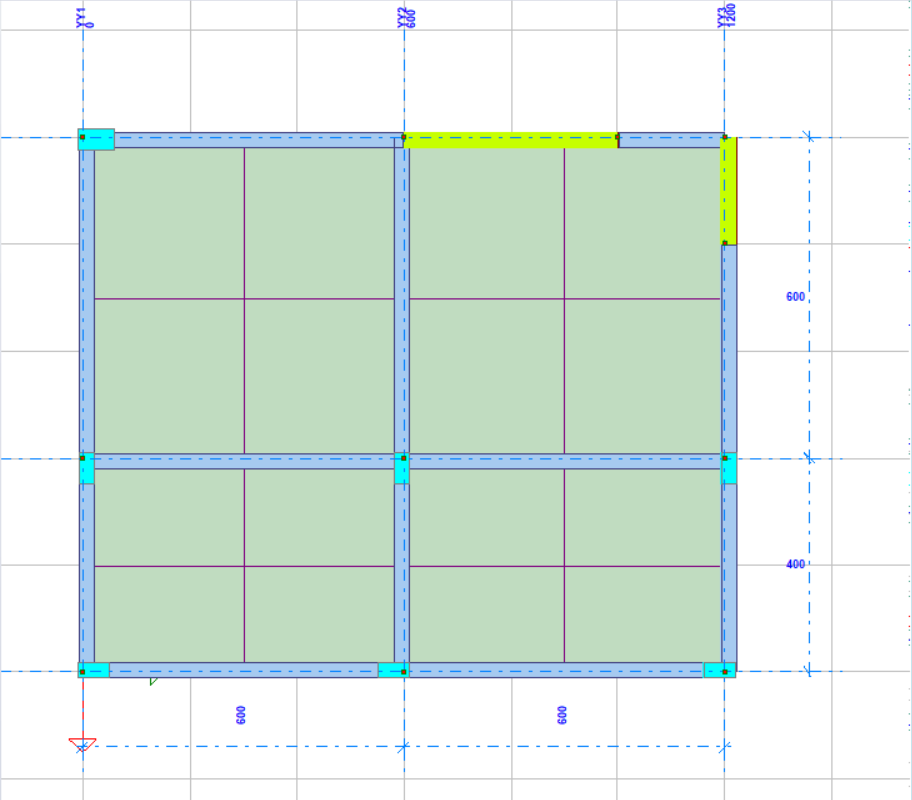
7. Saving and storeys
- When you save the project, the underlay is written into the project file and comes back when the project is opened. The path of the DXF file is not stored; deleting or changing the DXF afterwards does not affect the underlay in the project.
- If the DXF has changed, load it again: with “Replace the previous underlay on the storey” ticked, the new drawing replaces the old one.
- The underlay is per storey. When you change storey you see the underlay of that storey; nothing is drawn on a storey that has no underlay.
- When you start a new project, the underlay of the previous project is cleared.
File size: Because every line of the underlay is written into the project, a large sheet noticeably enlarges the file: the 4668-object sheet in the example adds about 0.75–0.95 MB to the project file; when only the axis, bond beam and wall layers (419 objects) are selected, it takes about a tenth of that. Switch off the layers you do not need and use “All storeys” only if it is really needed.
8. What is imported from the DXF?
| DXF object | Imported? | Remark |
|---|---|---|
| LINE | Yes | |
| LWPOLYLINE, POLYLINE | Yes | Straight segments as lines, curved segments as arcs |
| ARC, CIRCLE | Yes | |
| ELLIPSE, SPLINE | Yes | Split into short line segments |
| INSERT (block) | Yes | By exploding its content; including nested, rotated, scaled, mirrored and array blocks |
| DIMENSION | Partly | Dimension lines and arrows are imported, the dimension text is not |
| TEXT, MTEXT | No | The number is shown in the information line |
| HATCH | No | The number is shown in the information line |
| Image, 3D solid, region, etc. | No |
The supported file type is text (ASCII) DXF. DWG and binary DXF are not read; in this case the program gives a message asking you to save the file as ASCII DXF in the drawing program.
9. Tips for preparing the DXF file
- In AutoCAD select Save As → AutoCAD DXF (e.g. AutoCAD 2000/2004/2010 DXF); do not tick the “binary” option.
- Know the unit of the drawing (mm / cm / m). If you are not sure, measure an axis span.
- If possible, save each storey plan as a separate DXF and move one of the axis intersections to the (0,0) point of the drawing; then the underlay coincides with the model as soon as it is loaded.
- Switch off unnecessary layers (furniture, hatching, landscaping, dimensions) in the drawing or untick them from the list when loading.
- External references (XREF) do not enter the DXF; bind them to the drawing first.
- In very detailed sheets (tens of thousands of lines), importing only the layers that show the structural system lightens both the screen and the file.
10. Common situations
| Situation | Cause / solution |
|---|---|
| I loaded it but nothing appears on the screen | The underlay may be very far from the model: press Fit to screen. If it is still not there, the underlay may be hidden (Show) or loaded to another storey; look at the numbers in the bottom line of the window. |
| The underlay is much larger or smaller than the model | The drawing unit was selected wrongly. Load again with the correct unit or use Scale (two points). |
| The underlay is at the right scale but does not coincide with the model | Fit it with Move (two points); or load again with “Move the lower left corner of the drawing to the origin” and offsets. |
| Message “no objects to import in the selected layers” | No layer is ticked in the layer list, or the ticked layers contain only text/hatching. |
| Message that the file could not be read | The file is DWG or binary DXF. Save it again as ASCII DXF in the drawing program. |
| Texts and hatches did not come | Text and hatching are not imported (Section 8). For axis names, the circles and lines of the axis bubbles come. |
| I cannot select and delete an underlay line | The underlay is deliberately closed to selection. Delete all of it with Remove underlay; if you do not want a part of it, untick the relevant layer and load again. |
| No DXF lines in the right-click menu | You clicked on a member; right-click on an empty area or use File → Load DXF Underlay.... |
| The project file has become very large | Reduce the layers and load again; remove the underlay when modelling is finished. |