Creating a Structural Model from a DWG/DXF File with StatiCAD
1. Launch the StatiCAD program
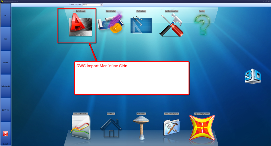
2. Enter the DWG Import menu
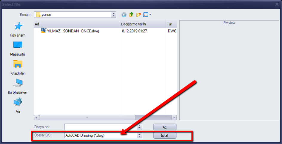
3. Use the File>Open command to open the File Open dialog box. Change the file type to dwg or dxf. Select your drawing file and use the Open command to display the drawing in the StatiCAD drawing editor. If the drawing file still cannot be displayed in the drawing editor after this operation, try saving the dwg file in dwg2007 format and opening it again in the StatiCAD drawing editor.
-
StatiCAD uses line objects during the import process.
-
- If you are using StatiCAD V6.0.9.0 or a later version, to convert polyline objects in the drawing to line objects, select the part of the drawing to be imported and click the Convert Selected Polylines to Lines command from the Modify menu. Alternatively, to simplify the entire drawing, click the Simplify Drawing for Import command under the Modify menu. The first operation converts polylines in the selected drawing section to lines. The second operation converts all polylines in the drawing to lines and deletes the remaining objects.
- If you are using a version prior to StatiCAD V6.0.9.0, before opening the drawing file in StatiCAD, explode the drawing in AutoCAD to convert polyline objects to line objects.
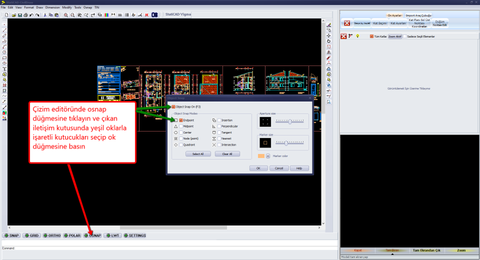
5. In the drawing editor, click the osnap button and in the dialog box that appears, select the Object Snap On and Endpoint options, then press OK.
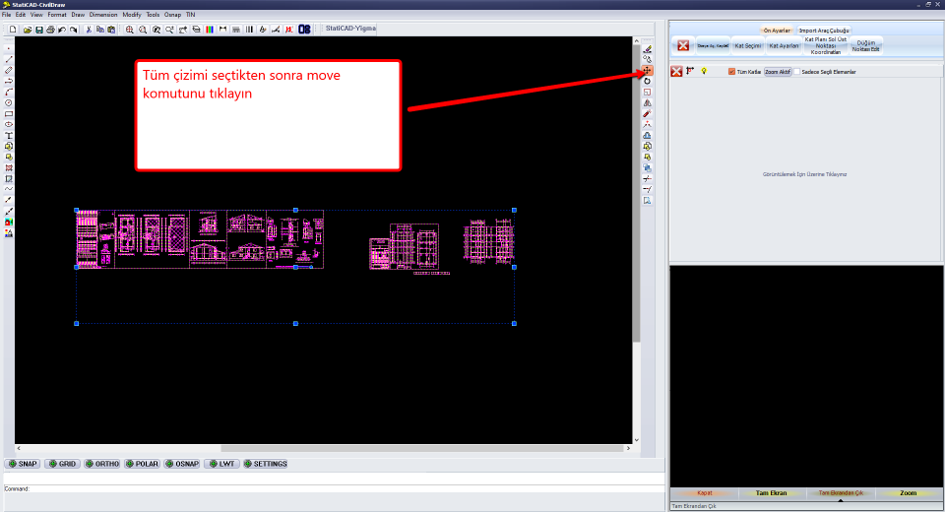
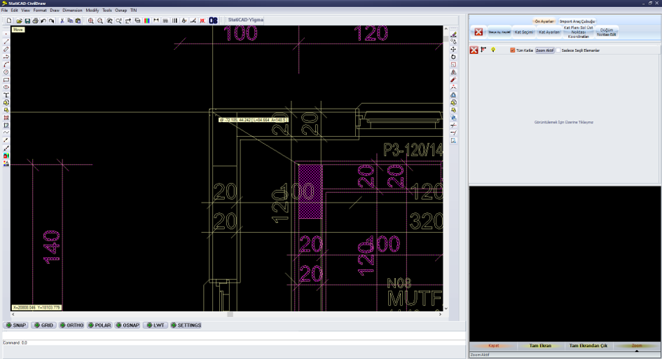
- After selecting the entire drawing with a window, click the Move command on screen (or Move from the Modify menu).
7. Click the upper-left point of the floor plan to be imported, press the Tab key on the keyboard, and type 0,0 in the command line that appears on screen. While typing zero comma zero, make sure the separator is a comma, not a period. Press Enter. The drawing will be moved to the 0,0 point based on the base point you marked.
(You can use the keyboard Tab key in the drawing editor to enter dimensions while any command is active — line, circle, move, copy, etc.)
8. Click the View>Zoom Extents command or the screen shortcut to display the entire drawing again. Press Esc to deselect the drawing.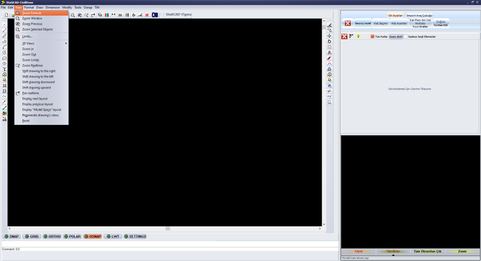
9. Use the Tools>Distance command to measure the distance between two points of known dimensions to determine whether the drawing was created in cm, mm, or m. If the dimensions are not in cm, select the drawing and use the Scale command to convert it to cm.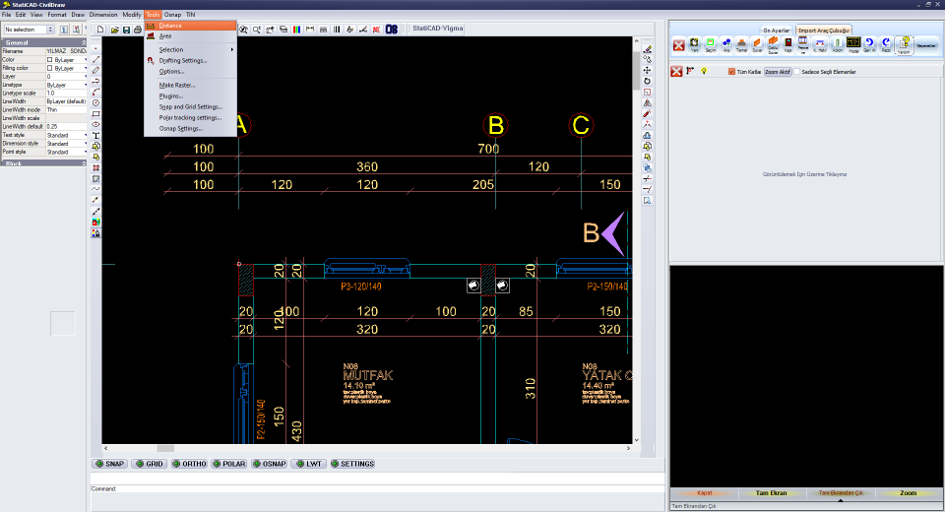
10. To hide layers you consider unnecessary in the drawing, select a line that belongs to that layer. Click on the Properties panel to find out the object's layer.
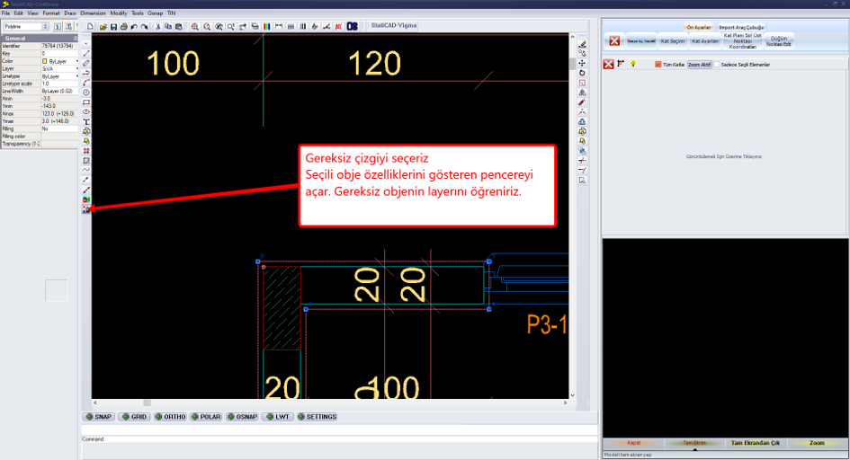
11. Use the Format>Layer dialog box to turn off the relevant layer.
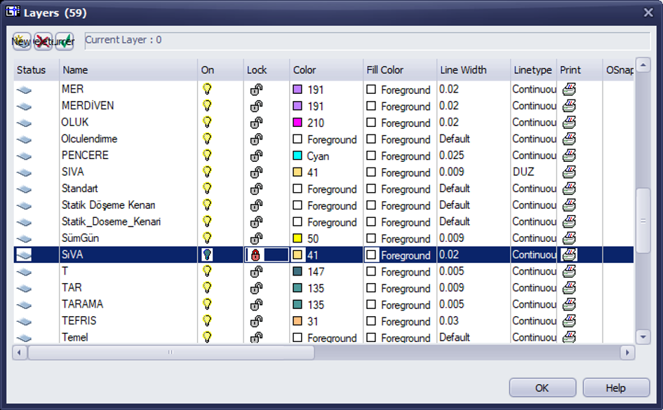
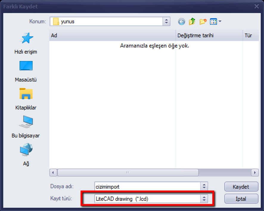
12. At this stage, you can take a backup of the edited drawing using the File>Save As command in dwg or lcd format. If saving in dwg format causes problems, save the drawing in lcd format.
13. On screen, storey settings, storey selection (which storey to import into), and general project settings are configured.

14. Click the Wall command on the Import toolbar. Importing walls one by one is more efficient; multiple wall import may not work well for every project.
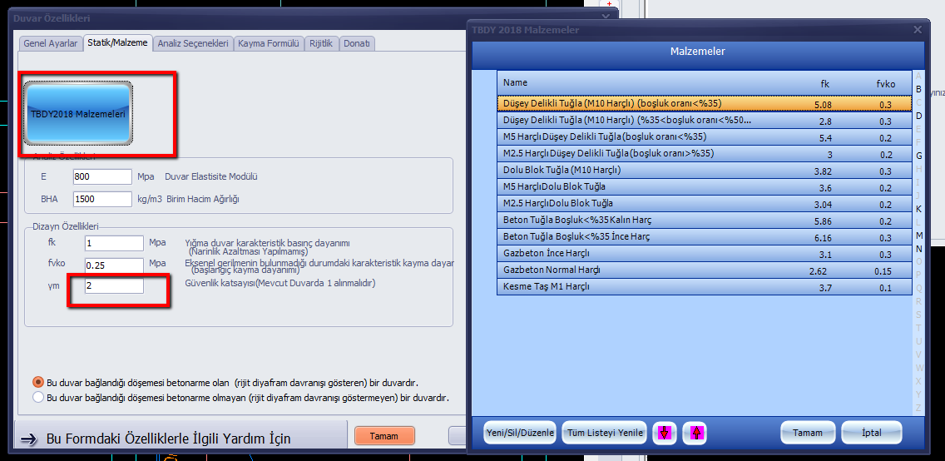
15. In the wall properties window that appears, change the appropriate values and select the material. If it is an existing storey or structure, set the safety factor to 1.
16. If our walls consist of lines (line, not polyline), we can start importing walls by selecting two lines at a time.
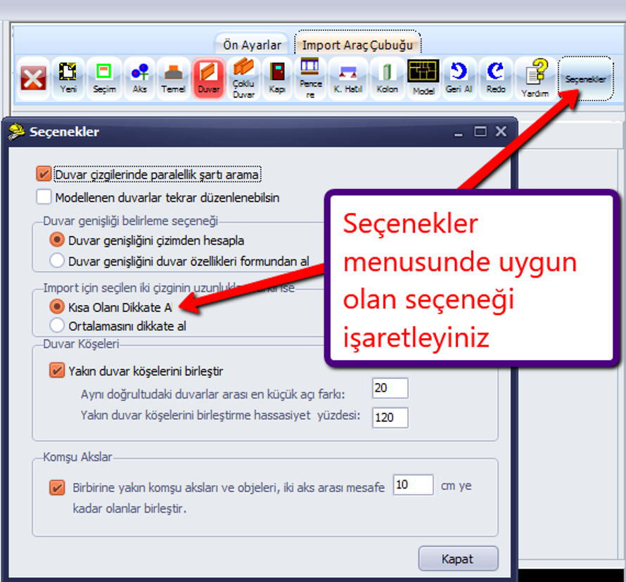
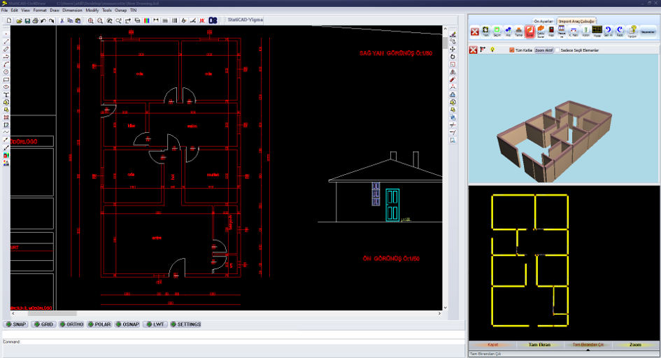
17. As the imported lines are converted to walls, the lines turn red.
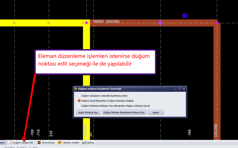
18. After the import process, wall corners and intermediate cross-sections may remain unconnected.
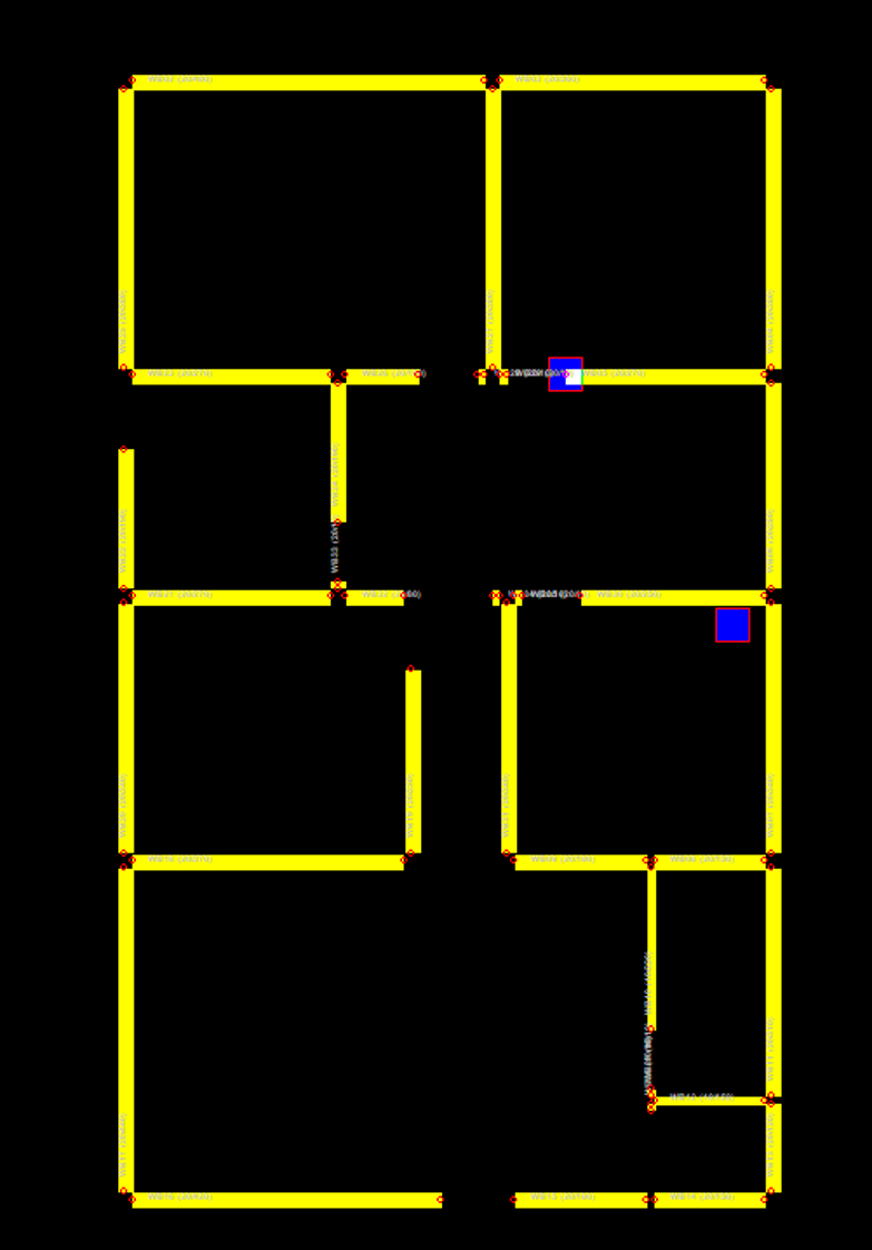
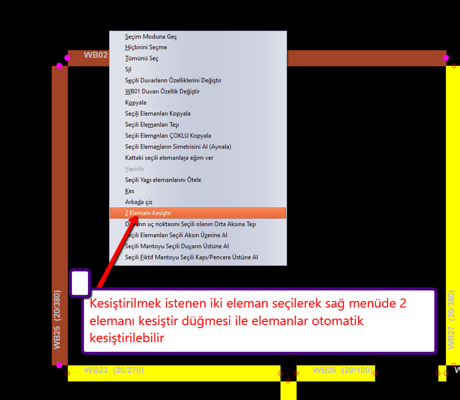
20. For this situation, select the two elements to be intersected on the main screen and use the Intersect 2 Elements button in the right-side menu to automatically intersect the elements.
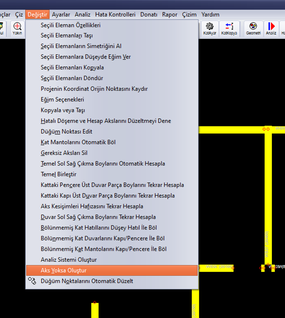
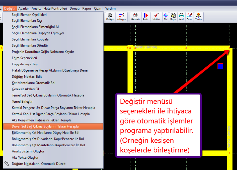
21. If grid lines (axes) have not been imported, they can be created automatically using the Create Axes if None Exist option in the Modify menu on the main screen.
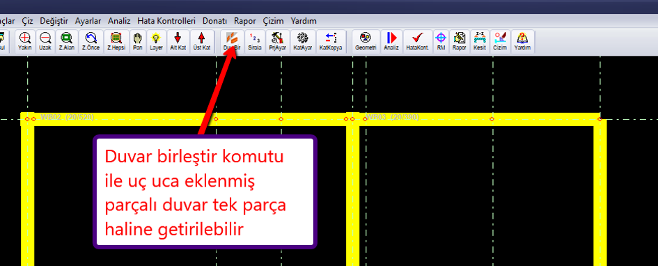
22. Using the Merge Walls command, segmented walls joined end-to-end can be combined into a single piece.
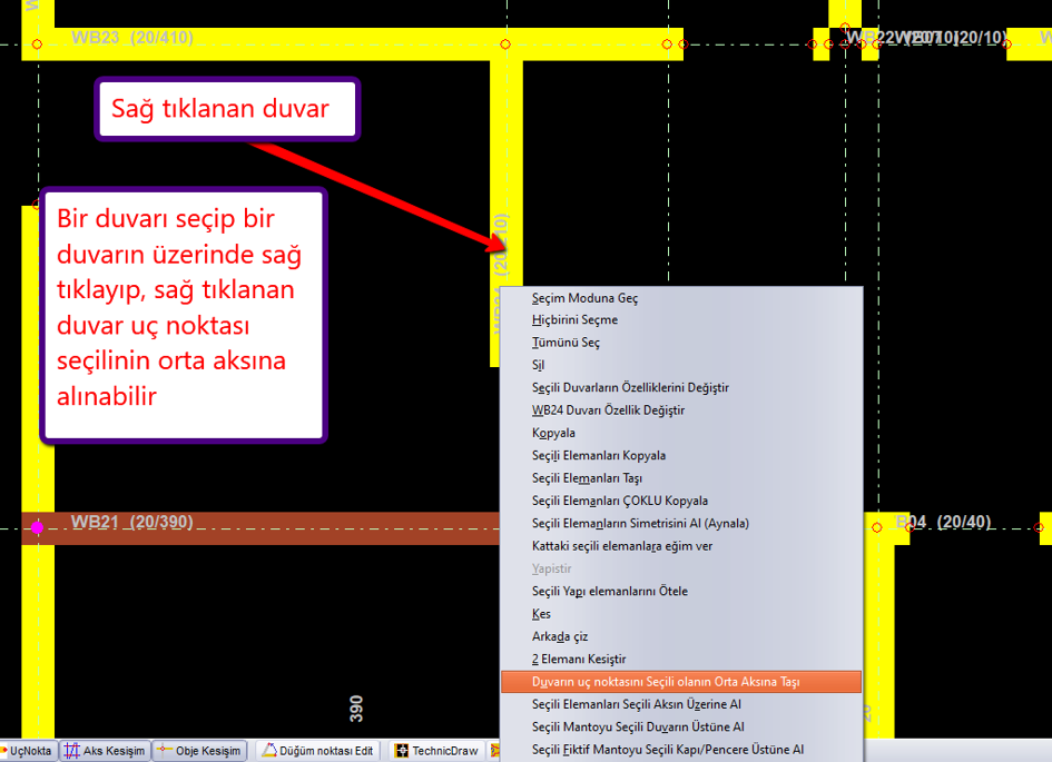
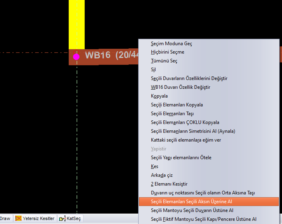
23. By selecting an axis and an element, you can use the Assign Selected Elements to Selected Axis option to perform the operation.
24. If there are incorrect elements, you can click or select them with a frame, delete them, and recreate them.
25. You can also import elements such as doors/windows, beams, vertical bond beams, and foundations by selecting two lines at a time, or you can draw them manually on the main screen.
26. You can import axes in bulk by selecting multiple axes at once.