Defining a Nonprismatic Beam
This article describes step by step how a beam whose section varies along its length (nonprismatic) is defined, drawn and modified in StatiCAD. For the other tools for precast structures, see the article Modeling Precast Structures.
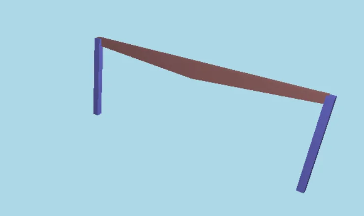
Figure 1 – Example: a 15 m nonprismatic beam seated on two columns, 3D view (the section is drawn segment by segment: 30/50 at the ends, 30/110 in the middle)
1. About this article
This article explains step by step how a beam whose section varies along its length is defined in StatiCAD. The workflow consists of five steps:
- opening the section library window (Section 3),
- defining the sections at the ends and in the middle of the beam as prismatic sections (Section 4),
- creating the nonprismatic section (Nonprismatic) from these sections (Section 5),
- drawing the beam with the nonprismatic section (Section 6),
- changing the properties of the beam or of the definition when necessary (Section 7).
The explanation is based on an example: a reinforced concrete roof beam with a 15 m span, 30/50 cm at the ends and 30/110 cm in the middle. The section hangs down from the top elevation of the beam: since the two end elevations are the same, the top edge is straight and the bottom edge slopes down towards the middle. The end section is named KU30x50, the middle section KO30x110 and the nonprismatic section CATI-DK.
Which editions? The nonprismatic section definition is available in all editions of StatiCAD.
The other tools for precast structures (precast section templates, connections, short corbel, crane) and the stiffness calculation of the nonprismatic section are described in the article Modeling Precast Structures.
2. What is a nonprismatic section?
A nonprismatic beam is modeled as a single member between two nodes. The section changes from one end of the beam to the other; the analysis builds the stiffness according to this actual variation. Roof truss beams, haunched beams and precast beams of varying depth are typical examples. There is no need to split the beam into short prismatic pieces and give each piece a separate section.
Figure 2 – Nonprismatic section definition of the example beam: two segments, end section → middle section → end section. The section hangs down from the top elevation of the beam. Schematic.
Roof beam with a sloping (double-pitched) top edge: In the program the section always hangs down from the top elevation of the beam; the top edge of a single beam is a straight line between its two end elevations. To model a beam whose top edge rises towards the ridge and whose bottom edge is straight, split the beam into two beams at the ridge, give each half a slope with Left Top Elevation / Right Top Elevation (e.g. 0 at the end, +60 cm at the ridge) and assign a single-segment nonprismatic section (e.g. KU30x50 → KO30x110). Since the depth increases by 60 cm, the bottom edge stays straight.
2.1 Segments
A nonprismatic section consists of one or more segments. Each segment has a start section, an end section and a length. The segments are arranged in order from end 1 to end 2 of the beam. Within a segment, the section changes smoothly from the start section to the end section.
- The start and end sections must be prismatic sections saved in the library: polygon or precast template sections. A nonprismatic section cannot be a segment of another nonprismatic section.
- The end section of a segment is normally the start section of the next segment. A double-pitched beam is therefore defined with two segments: KU30x50 → KO30x110 and KO30x110 → KU30x50.
- A region where the section stays constant is given with a segment whose start and end sections are the same (e.g. KU30x50 → KU30x50).
2.2 Length type
Table 1 – Length types
| Type | Meaning of the Length column |
|---|---|
| Variable (proportional) | A unitless weight. The Absolute segments are subtracted from the beam length; the remaining length is shared among the Variable segments in proportion to these weights. 1 and 1, or 2 and 2, give the same result: two equal segments. |
| Absolute (fixed length) | The length of the segment, in cm. This segment stays the same even if the length of the beam changes. |
For example, if constant-section regions of 50 cm are wanted at the ends, four segments are entered: KU30x50 → KU30x50 (50, Absolute), KU30x50 → KO30x110 (1, Variable), KO30x110 → KU30x50 (1, Variable), KU30x50 → KU30x50 (50, Absolute). In a 15 m beam, each of the two middle segments becomes (15 − 1) / 2 = 7 m. If the same definition is assigned to a 12 m beam, the middle segments automatically become 5.5 m.
Total length: The sum of the segment lengths is always scaled to the length of the beam. If the definition consists only of Absolute segments and their sum differs from the beam length, the segments are lengthened or shortened proportionally. If the sum of the Absolute segments exceeds the beam length, the Variable segments get zero length. For definitions that will be used on beams of different lengths, prefer the Variable type.
2.3 Stiffness variation
The EI33 Variation and EI22 Variation columns determine how the flexural stiffness varies within a segment. EI33 is the bending of the beam in the vertical plane (strong axis), EI22 the bending in the horizontal plane (weak axis). The area, the torsional constant and the shear areas always vary linearly.
Table 2 – Stiffness variation options
| Option | Quantity that varies linearly | When? |
|---|---|---|
| Linear | I | The dimension of the section along this axis is constant and the other dimension varies. In the example, EI22: the width is constant (30 cm), and I22 = h·b³/12 increases linearly with the depth. |
| Parabolic | √I | An I section dominated by its flanges, with varying depth (I increases approximately with h²). |
| Cubic | ∛I | A rectangle of constant width whose depth varies linearly. In the example, EI33: I33 = b·h³/12. |
The I values of the end sections are matched exactly in every case; the option affects only the values in between. If you are not sure, select Cubic (solid section) or Parabolic (I section) for the axis in which the depth of the section varies, and Linear for the axis in which it does not.
3. Step 1 – Opening the section window
Sections are defined in the Frame Member Section Properties window. This window is reached from the beam properties window:
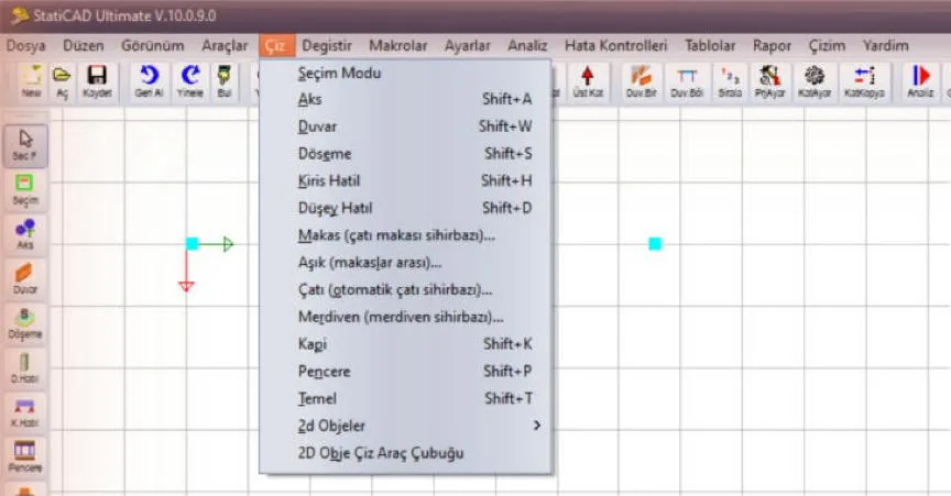
- From the menu, select Draw › Beam / Bond Beam (shortcut Shift+H, or the K.Hatıl (Bond Beam) button on the left).
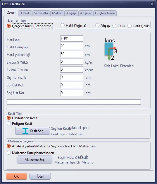
- In the Bond Beam Properties window that opens, select Frame Beam (Reinforced Concrete) as the Element Type.
- Press the Select Section button in the Section Type group.
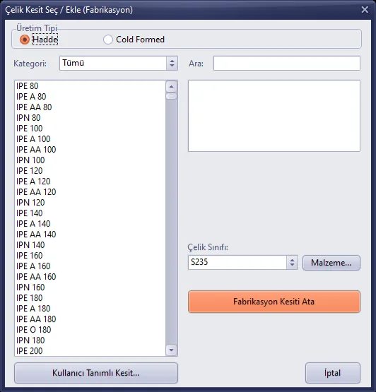
- The steel section (fabrication) window opens first. Press the User-Defined Section... button at the bottom left.
The Frame Member Section Properties window shows two lists:
- Saved frame cross sections (in the middle): the section library. The sections here can be used in all projects.
- Frame cross section used in the project (on the right): the sections used in this project. When a library section is assigned to a member, it is copied to this list automatically, together with its segments in the case of a nonprismatic section.
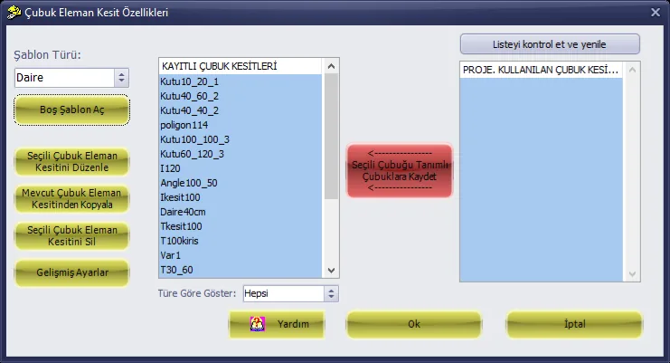
Figure 6 – Frame Member Section Properties
Table 3 – Buttons of the window
| Button / box | Function |
|---|---|
| Template Type + Open Blank Template | Opens a new section definition of the selected type (Polygon, Nonprismatic, Precast I …). |
| Edit Selected Frame Section | Opens the section selected in the list in its own editor (Section 7.2). |
| Copy from Existing Frame Section | Creates a copy of the selected section (Section 7.3). |
| Delete Selected Frame Section | Deletes the selected section from the library. |
| Show by Type | Filters the library list by type (e.g. Nonprismatic only). |
| Ok | Assigns the section selected in the list to the member and closes the window. |
4. Step 2 – Defining the end and middle sections
The sections to be used in the segments of the nonprismatic section are first defined as prismatic sections. The example needs two sections: KU30x50 and KO30x110. For each of them:
- Select Polygon in the Template Type list.
- Press Open Blank Template. The Polygon window opens.
Precast template sections (Precast I, Trapezoidal …) can also be used as segments; their definitions are in Section 2 of the article Modeling Precast Structures.
4.1 Name and material
On the Section Parameters tab, type the name of the section (KU30x50) in the Name row. Select the material with Select Material; in the example, C14 B420C reinforced concrete. The base point and the angle can be left empty (0).
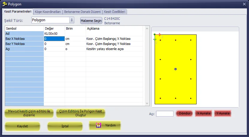
Figure 7 – Section Parameters: name and material
4.2 Corner coordinates
On the Corner Coordinates tab, type the number of corners (4) in the n box, enter the X, Y coordinates of the corners (cm) in the table and press Get vertex coordinates from table. The preview is updated. The corners are (0, 0), (30, 0), (30, 50), (0, 50) for KU30x50 and (0, 0), (30, 0), (30, 110), (0, 110) for KO30x110.
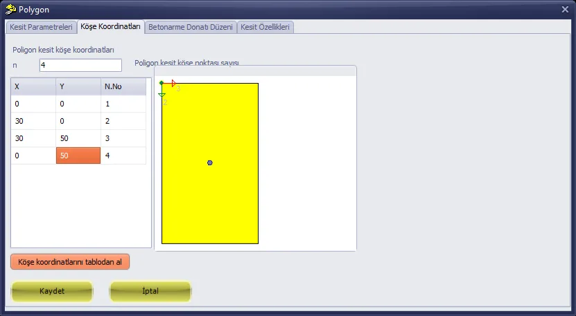
Figure 8 – Corner coordinates (KU30x50)
Corner order: In the design, the intermediate sections are generated by matching the corners of the end sections by their sequence number: corner 1 of the start section moves towards corner 1 of the end section. Enter the two sections of a segment with the same number of corners and in the same order (starting from the same corner and going round in the same direction). In the example, both sections start at corner (0, 0) and go round in the same direction. If the numbers of corners differ, the extra corners are ignored.
4.3 Reinforcement layout
On the RC Reinforcement Layout tab, enter the Cover and press Calculate automatic reinforcement layout. The reinforcement lines (number, diameter, start and end coordinates) are written to the table and shown in the preview. You can also enter the lines by hand.
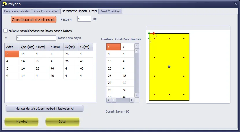
Figure 9 – Automatic reinforcement layout
A reinforcement layout is required: The reinforcement of a nonprismatic reinforced concrete beam is calculated from the reinforcement layouts of the segment sections. In a prismatic polygon beam, the analysis generates the reinforcement layout itself if it is empty; it does not do so for a nonprismatic section. If one of the segment sections has no reinforcement layout, the beam is not designed and the analysis gives a warning (Section 9). Like the corners, the reinforcement lines are matched by sequence number; create the lines in the same order in both sections. The automatic layout keeps this order by itself in sections of the same shape.
4.4 Saving
Press Save. The section is added to the library list. Repeat the same steps for KO30x110.
The blank template may show the previous section: Open Blank Template may open the Polygon window with the corners and reinforcement of the previous polygon. When moving on to the second section, check the name, n and the corner table, press Get vertex coordinates from table and recalculate the reinforcement layout.
5. Step 3 – Defining the nonprismatic section
5.1 Opening the editor
Select Nonprismatic in the Template Type list and press Open Blank Template. The Nonprismatic Section Definition window opens.
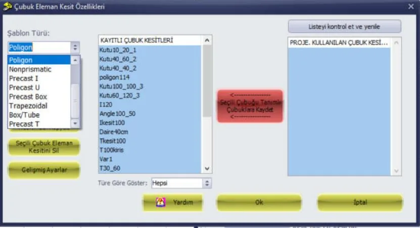
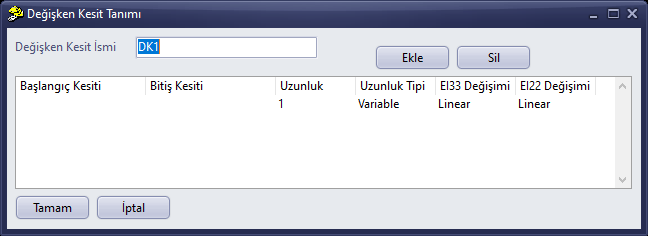
Figure 11 – Nonprismatic Section Definition: new definition
A new definition opens with an unused name (DK1, DK2 …) and a single default row: length 1, Variable, Linear, Linear. The start and end sections are empty.
5.2 Entering the segments
- Type the name in the Section Name box: CATI-DK.
- Click the Start Section cell of row 1 and select KU30x50 in the list that opens. The list shows the sections in the library.
- Select KO30x110 in the End Section cell.
- Type 1 in the Length cell (the decimal separator can be a point or a comma). Leave Length Type as Variable.
- Select Cubic for EI33 Variation and Linear for EI22 Variation (Section 2.3).
- Open a second row with Add and enter KO30x110 → KU30x50, 1, Variable, Cubic, Linear.
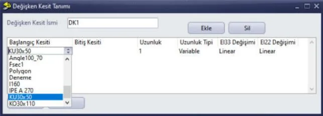
Figure 12 – Selecting the start section from the list
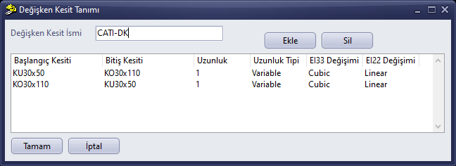
Figure 13 – The completed definition of the example
Table 4 – Example definition (CATI-DK)
| Row | Start Section | End Section | Length | Length Type | EI33 | EI22 |
|---|---|---|---|---|---|---|
| 1 | KU30x50 | KO30x110 | 1 | Variable | Cubic | Linear |
| 2 | KO30x110 | KU30x50 | 1 | Variable | Cubic | Linear |
Add appends a new row with the default values at the end. Delete deletes the selected row; at least one row remains in the definition, and the last row cannot be deleted.
5.3 OK and the checks
Press OK. The following checks are made before saving; if there is a problem, a message appears, the window stays open, and you can correct the problem and press OK again:
- The name cannot be empty and cannot be the same as the name of another section in the library.
- There must be at least one segment.
- The start and end sections of each segment must be sections saved in the library that are not nonprismatic.
- The length of each segment must be a number greater than zero.
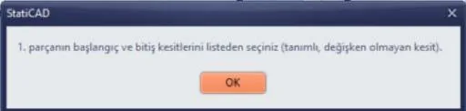
Figure 14 – Message for a segment whose sections have not been selected
On saving, the equivalent prismatic properties of the definition (area, moments of inertia, torsional constant, shear areas) are also calculated: the average of the end sections, weighted by the segment lengths. The self-weight and the mass are found with this average area (Section 8). The stiffness of the beam, on the other hand, is built not with the average but with the actual profile.
After saving, the definition appears in the library list. If Nonprismatic is selected in the Show by Type box, the list shows only the nonprismatic sections.
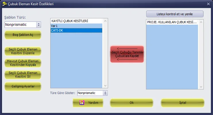
Figure 15 – Nonprismatic sections in the library
6. Step 4 – Drawing the beam
6.1 Selecting the section
- Select CATI-DK in the library list of the Frame Member Section Properties window.
- Press Ok. The window closes and you return to Bond Beam Properties.
In Bond Beam Properties, Polygon Section is checked automatically. Selected Section becomes CATI-DK and Section Type becomes Nonprismatic.
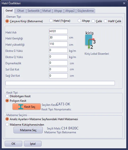
Figure 16 – Properties of a beam with a nonprismatic section assigned
- The Bond Beam Width and Bond Beam Height boxes are filled from the section. For a nonprismatic section, these values are the dimensions of the end section of segment 1 (in the example KO30x110 → 30 / 110). In plan, the beam is drawn with this width; the analysis and the design, however, use the nonprismatic profile.
- Left Top Elevation and Right Top Elevation are the end elevations of the beam; they are not related to the variation of the section.
- The option in the Material Selection group does not change; the material of the beam is determined from this group.
Press OK.
6.2 Drawing and profile direction
Click the two ends of the beam in plan. The beam is drawn and shown in the 3D view (Figure 1). The 3D view draws the section segment by segment, each with its own start and end sections; the 3D view on the main screen and the 3D View window use the same rule. To draw other beams with the same properties, you can keep clicking.
Profile direction: end 1 → end 2: The start section of row 1 of the definition is placed at end 1 of the beam (the Left Top Elevation end in the properties window), and the end section of the last row at end 2 (the Right Top Elevation end). Which end is end 1 is determined by the position of the beam, not by the drawing direction: in a beam in the X direction and in an inclined beam, the end with the smaller X is end 1; in a beam in the Y direction, the end with the larger Y (the lower end in plan) is end 1.
With a symmetric profile, as in the example, the direction does not matter. With an asymmetric profile (e.g. a mono-pitch beam), check the direction in the 3D view: the profile is drawn segment by segment starting from end 1. If it comes out reversed, create a second definition in which the order of the segments and their start/end sections are reversed.
7. Step 5 – Changing properties
7.1 Changing the section of a beam
To assign a nonprismatic section to a beam that has already been drawn, or to change its section:
- Right-click the beam and select <name> Beam Bond Beam Properties Change (in the example, HB01 Beam Bond Beam Properties Change).
- In the Bond Beam Properties window, open the section window with Select Section › User-Defined Section....
- Select the new section and press Ok, then press OK in the properties window.
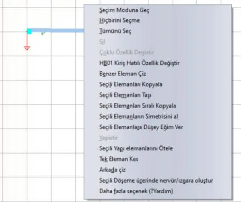
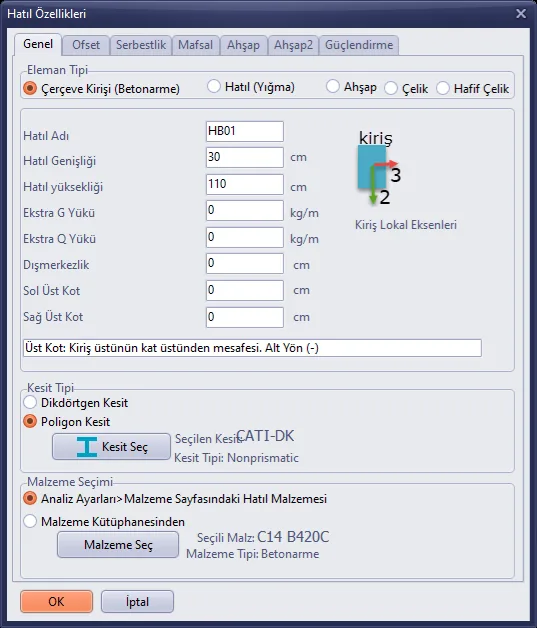
To make the beam prismatic again, check Rectangular Section and enter the dimensions, or select another polygon section. If several beams are selected, Multiple Property Change in the right-click menu opens the same window for all the selected beams.
7.2 Editing the definition
To change the segments, the lengths or the stiffness variation of a nonprismatic section:
- Open the Frame Member Section Properties window (Section 3) and select the definition (CATI-DK) in the library list.
- Press Edit Selected Frame Section. The editor opens with the rows of the definition.
- Change the rows, use Add / Delete if necessary, and press OK.
- Close the section window with Ok.
The change applies to all beams: The definition is shared by all the beams that use it; editing it changes all of them together. To change only some of the beams, make a copy of the definition (Section 7.3) and assign the copy to those beams.
When editing, do not change the name of the definition: the beams find their section by its name; if the name changes, the beams that carry the old name are left without a section. If a new name is needed, create a copy and assign the new section to the beams.
For the edit to be transferred to the project, close the section window with Ok, then run the analysis again.
If you have changed a segment section: If you edit a section that is used as a segment (e.g. KO30x110), the stiffness and the reinforcement design are carried out with the new section in all the nonprismatic sections that use it. The equivalent area used for the self-weight, however, is calculated when the nonprismatic section definition is saved: after changing a segment section, save the nonprismatic section again with Edit Selected Frame Section › OK.
7.3 Copying and deleting
- Copy from Existing Frame Section creates a copy of the selected definition with all its segments. Give the copy a new name.
- Delete Selected Frame Section deletes the definition from the library. A section that is used as a segment of a nonprismatic section cannot be deleted; you are asked to change or delete that definition first (Section 9).
8. Analysis and design
No additional setting is needed for a nonprismatic beam; the analysis, the SAP2000 export, the design and the drawings use the nonprismatic section automatically.
8.1 Finite element model
- Stiffness: in the finite element model, the beam is a single nonprismatic member. The stiffness matrix and the fixed-end forces are found by integration along the profile (see Modeling Precast Structures, Section 3). The axis of the member is a straight line between its two end nodes; the section properties vary along this axis.
- Split beam: in the model, the beam may be split into several pieces by intermediate nodes or by the slab mesh. In this case each sub-element takes the slice of the profile at its own position.
- Self-weight: the total self-weight of the beam is found with the equivalent average area (in the example (0.15 + 0.33) / 2 = 0.24 m²) and is distributed to the finite element pieces in proportion to their section areas: the deep region carries more load. As in a rectangular beam, the total is calculated with the length of the beam axis and the unit mass of the material (in the example 0.24 m² × 15 m × 2500 kg/m³ = 9.0 t = 88.3 kN).
- Mass: the element mass matrix is built with the area of each piece.
Old projects: In versions before V.10.1.0.0, the equivalent area of the nonprismatic section is not saved to the file, and in these versions the self-weight and mass of nonprismatic beams do not enter the analysis. When such a project is opened, these values are calculated automatically at first use. In old projects that contain nonprismatic beams, run the analysis again and review the results.
8.2 Reinforced concrete design
- Reinforcement: the flexural reinforcement is calculated at three sections: left end, mid-span and right end. These sections are generated by interpolation between the corners and reinforcement lines of the segment sections; therefore the reinforcement layouts of the segment sections must be defined (Section 4.3).
- Moment capacity Mr: calculated at six positions (left and right support top/bottom, span bottom/top) with the actual outline of the section and the selected reinforcement: the TS 500 equivalent rectangular stress block (0.85·fcd, depth k1·c) is clipped to the polygon, the steel is elastic–perfectly plastic, N = 0. If the design moment exceeds Mr, an error is written.
- Shear: the same method as for rectangular beams is used. With high and mixed ductility, the capacity shear is Ve = Vdy + (Mpi + Mpj) / ℓn (Mp = 1.4·Mr, both directions); with limited ductility, Vd. The confinement zone is calculated with the less favourable of the two end sections (smallest depth and web width), the middle zone with the mid-span section; the confinement zone length 2·h is taken with the larger end depth.
- Checks: Ve (Vd) ≤ 0.85·bw·d·√fck; with limited ductility also Vd ≤ 0.22·bw·d·fcd; Vr ≥ Ve; stirrup spacing required for shear ≥ 50 mm; Md ≤ Mr. A condition that is not satisfied is written as an error to the report row of the beam and to the project checklist (Section 9).
Details are in Section 3 of the article Precast Connection Design.
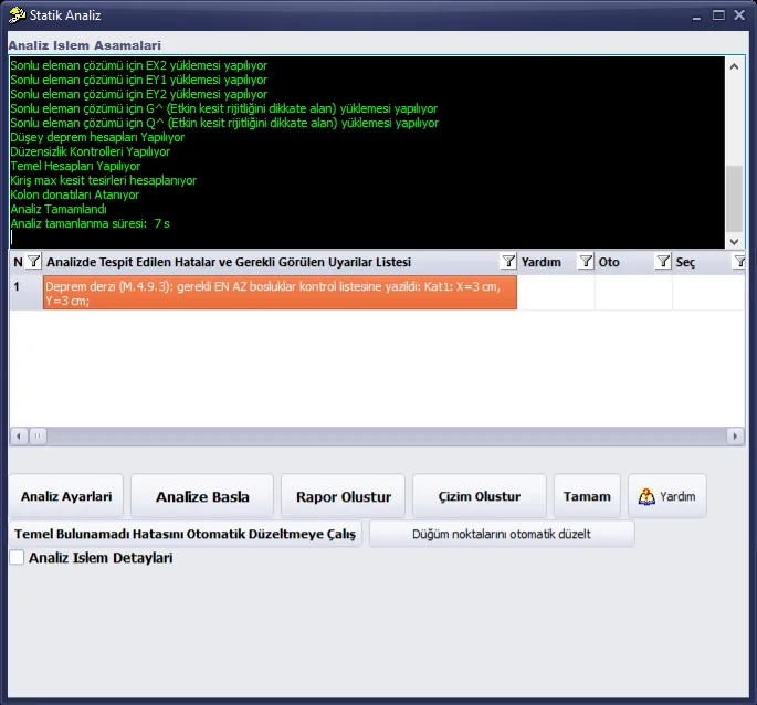
Figure 19 – Analysis of the example: since the reinforcement layouts of the segment sections are defined, there is no warning about the nonprismatic section (the list contains only the seismic joint information)
8.3 Development and section drawing
In the beam development (the reinforcement elevation drawing of the beam), the bottom edge of the beam is drawn as a broken line along the profile (h(x)). The stirrups are drawn with the depth at their location and the straight bottom bars parallel to the bottom edge; the hook lengths of the straight bars are taken from the end section depth. The section view is generated at the station where section mark A-A is placed in the development: the section outline and the reinforcement points are interpolated from the segment sections, and the label gives the distance of the station from the left grid line and the name of the nonprismatic section. The section mark is also drawn over the depth at that point.
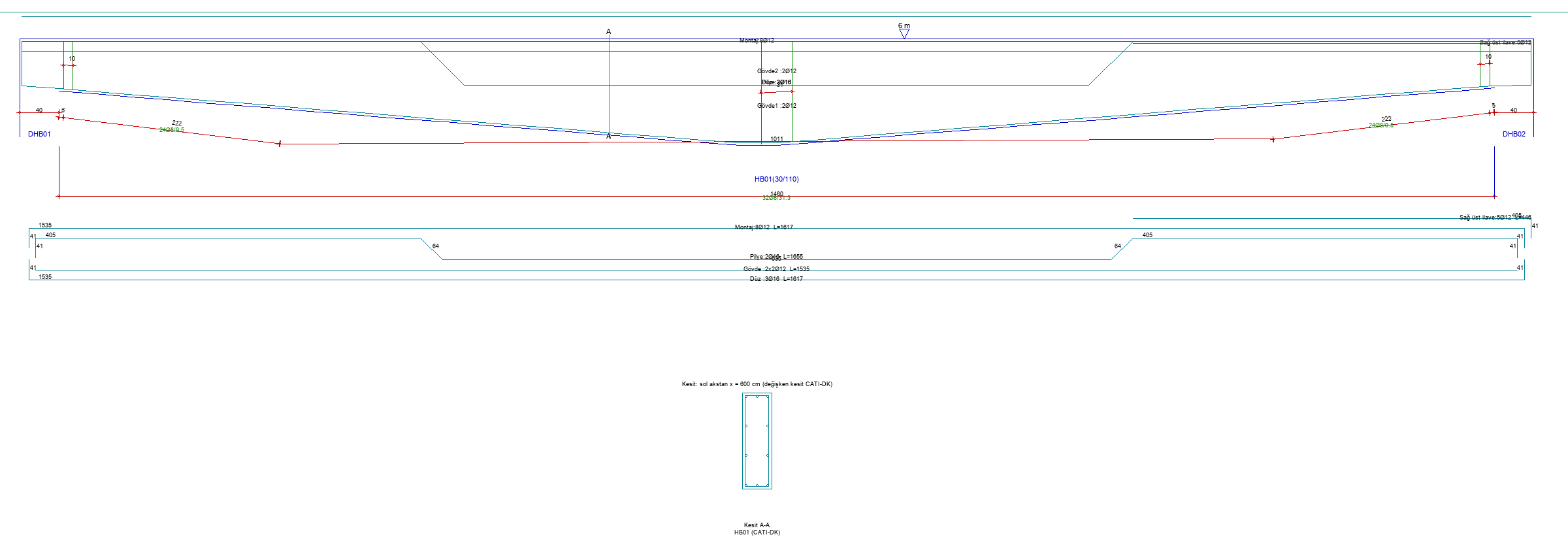
Figure 20 – Development of the example beam and section A-A (600 cm from the left grid line, h ≈ 98 cm)
8.4 Verification with SAP2000
The example frame (two 40/40 columns, h = 6 m, a 15 m nonprismatic beam) was built independently in SAP2000 v27 with SAP’s own nonprismatic section definition (Nonprismatic), and the results were compared (axis offset off; in SAP the self-weight was applied with the actual area distribution, its total made equal to that of StatiCAD; in the modal analysis, effective section modifiers of 0.35 for the beam and 0.70 for the columns):
Table 5 – StatiCAD / SAP2000 comparison (G load case and modal)
| Quantity | StatiCAD | SAP2000 | Difference |
|---|---|---|---|
| Beam end moment (kNm) | −43.41 | −43.22 | 0.4% |
| Mid-span moment (kNm) | 142.73 | 143.01 | 0.2% |
| Mid-span deflection (mm) | 5.03 | 5.11 | 1.7% |
| TX (s) | 0.381 | 0.382 | 0.3% |
| TY (s) | 0.584 | 0.585 | 0.1% |
9. Warning and error messages
Table 6 – Messages and what to do
| Where | Message | What to do |
|---|---|---|
| Editor, OK | The section name cannot be empty. | Type a name. |
| Editor, OK | A section with this name already exists: <name> | Give another name. |
| Editor, OK (when editing an old definition that has no segments left) | Define at least one segment (Add). | Open a row with Add and fill it in. |
| Editor, OK | Select the start and end sections of segment N from the list (a defined, prismatic section). | Select the cells from the list. If the section is not in the library, define it first (Section 4). |
| Editor, OK | The length of segment N must be a number greater than zero. | Correct the length. |
| When selecting a column / post section | A nonprismatic (variable) section can be assigned to beams only. Select a prismatic section for the column. | Assign a prismatic section to the column. |
| When deleting a section | Section <section> is used as a segment of the nonprismatic section <definition>; change or delete that definition first. | First change or delete the nonprismatic section definition. |
| Analysis warning list | Warning: the section profile of N nonprismatic beam(s) could not be resolved (…); these beams were analysed as prismatic. … Beams (storey:name): … | Open the section definition of the beams named in the list; check that the segment sections exist in the library and that the lengths are valid. Run the analysis again. |
| Analysis warning list | <beam> poligon/degisken kesitli kiris icin donati duzeni cozulemedi; kesit editorunde Betonarme Donati Duzeni tanimlayin (shown in Turkish: the reinforcement layout of the polygon/nonprismatic beam could not be resolved; define the reinforcement layout in the section editor) | Create the reinforcement layout in each of the segment sections (Section 4.3). Run the analysis again. |
| Beam report row and project checklist | … design moment at … Md=… kNm exceeds the moment capacity Mr=… kNm with the selected bars | Increase the reinforcement or the section. |
| Beam report row and project checklist | … the shear force … kN exceeds the upper limit 0.85*bw*d*sqrt(fck)=… kN (TBDY 7.4.5.4); with limited ductility also 0.22*bw*d*fcd (TS 500 8.1.5) | Enlarge the section (especially the end section depth or the web width). |
| Beam report row and project checklist | … the shear resistance in the support zone Vr=… kN is less than the design shear … kN; or the stirrup spacing required for shear is below 50 mm | Increase the stirrup diameter / number of legs or the section. |
10. Limits and tips
- Beams only: a nonprismatic section cannot be assigned to columns and posts.
- The plan width is taken from the end section of segment 1 (Section 6.1).
- Report: in the section information of the report, only the first segment of the nonprismatic section is shown.
- Total self-weight: in definitions that mix Absolute and Variable segments, the equivalent average area is approximate, because the actual length of the Variable segments depends on the beam. The distribution and the stiffness are not affected by this approximation.
- Development: the section view is drawn at a single station (the location of mark A-A); the stirrup development and the quantity takeoff use a single stirrup length (from the Bond Beam Height value of the beam), whereas in reality the stirrup length varies along the beam. The bend heights of the bent-up bars are taken from the end section.
- Renaming: if the name of the definition is changed while editing, the beams are not updated (Section 7.2).
- Library: the definitions are saved to the section library and can be selected in all projects.
The model and inputs in the example are for illustration purposes only; the accuracy of the sections, loads and results is the responsibility of the engineer in charge of the project.