Important Considerations in Reinforced Concrete Building Modeling with StatiCAD
Reinforced concrete analysis and design features were introduced to the program with StatiCAD Ultimate 6.2.0.0.
Only the analysis and design of newly constructed reinforced concrete buildings can be performed.
Begin your project by first configuring the storey settings. For detailed information, click the following link: General Storey Settings.
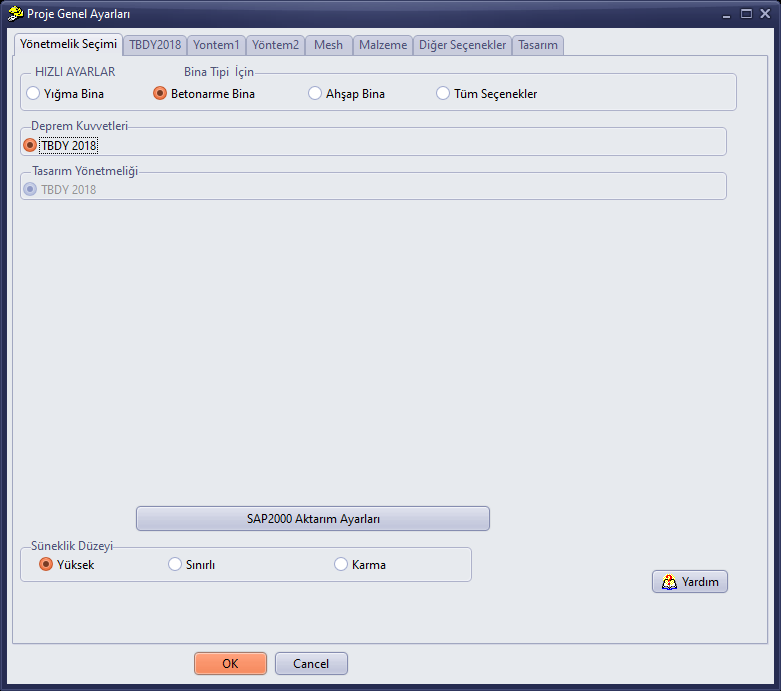
In the Code Selection tab of the Project General Settings window, select the Reinforced Concrete Building option as the building type and choose the ductility level you wish to design for.
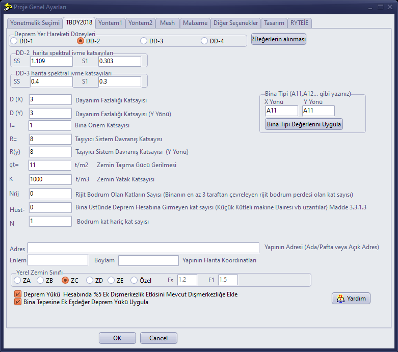
In the TBDY2018 tab, enter the SS and S1 values for the DD-2 and DD-3 earthquake levels. For information on how to obtain these values, you can review the article at OBTAINING TBDY2018 EARTHQUAKE PARAMETERS (SS, S1).
The SS and S1 values entered for DD-2 are used to calculate earthquake forces, while the values entered for DD-3 are used in the calculation of the lambda coefficient in the inter-storey drift limitation calculation.
Enter the building type code (such as A11, A12) in the relevant field and press the Apply Values button; building type codes affect the code-based calculations that depend on building type during analysis.
The R and D coefficients and the permitted BYS values are retrieved from the table when the Apply Values button is pressed. If necessary, modified values are used when the button is pressed again.
The soil bearing capacity stress, local soil class, and subgrade reaction coefficient values are obtained from the geotechnical report (soil investigation report).
The number of storeys excluding the basement is used in the soft storey calculation.
The address/latitude/longitude information is printed in the report for informational purposes only.
The 5% additional eccentricity option must be selected for calculations of new buildings.
In the Method 1 tab, under the Earthquake Load Calculation Option for Storeys, you can choose the equivalent earthquake load method or modal analysis. With the finite element modal analysis option, you can select the analysis type as with or without a rigid diaphragm.
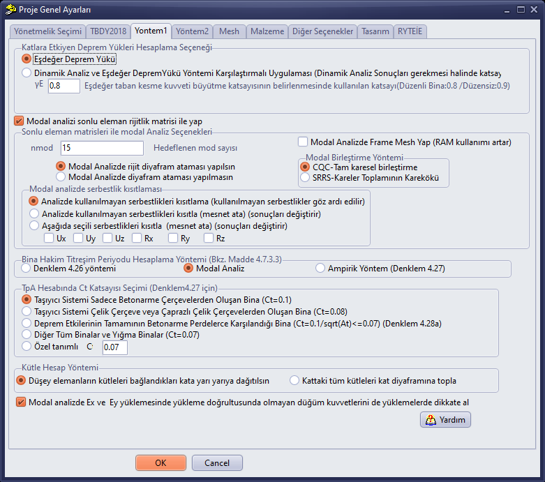
If you select the equivalent earthquake load method, you can determine the dominant vibration period of the building either by modal analysis, which is a more precise calculation method, or by the empirical formulas given in clause 4.7.3.4.
When dynamic analysis is selected and the gammaE value is set to 0.8, if A1 irregularity is detected as a result of the analysis, a message is displayed on the project error check page (report page 3) and in the A1 Torsional Irregularity report indicating that the gammaE value must be taken as 0.9. In such a case, re-running the analysis with gammaE set to 0.9 resolves the issue.

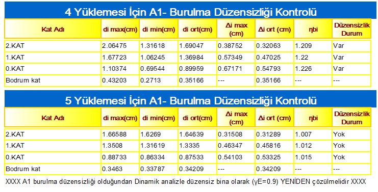
Within the scope of TBDY2018, the dominant vibration period of the building can be calculated via TPA under the following conditions.

Selecting shell finite elements as the Load Transfer Option for Slabs is beneficial for a more realistic calculation of beam torsion reinforcement and for a more precise transfer of vertical loads through slabs, but it increases the analysis time.
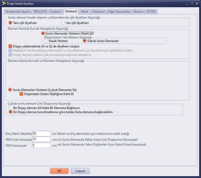
In the Mesh tab, you can adjust the shell element mesh parameters. For detailed information, click Slab Finite Element Mesh Option.
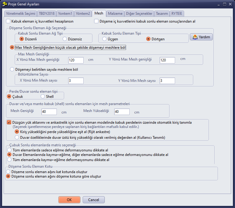
In the Material tab, you can set the material types to be assigned to elements. For different material types, material assignment can be made from the column, beam, and shear wall properties.
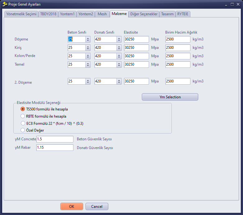
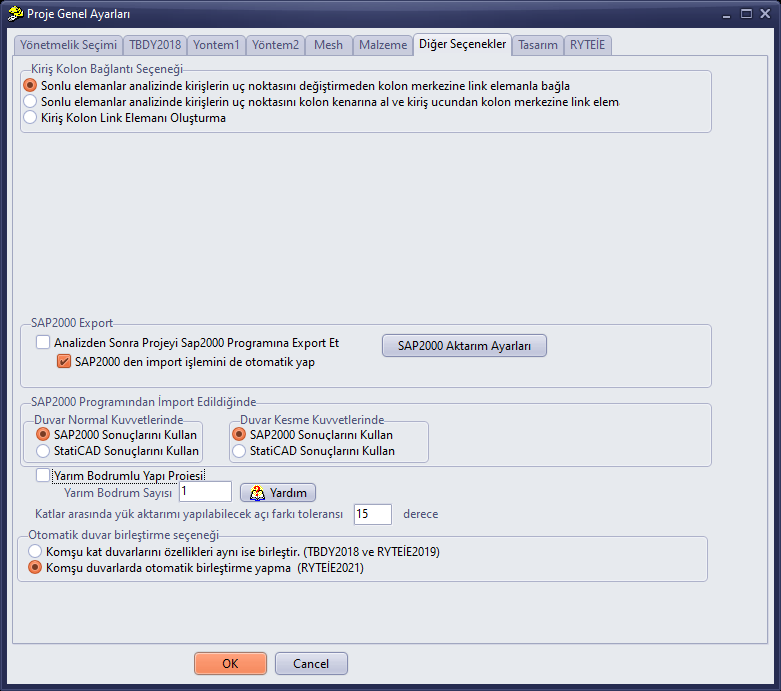
If your building has a half-basement, the half-basement building project option in the Other Options tab must be selected.
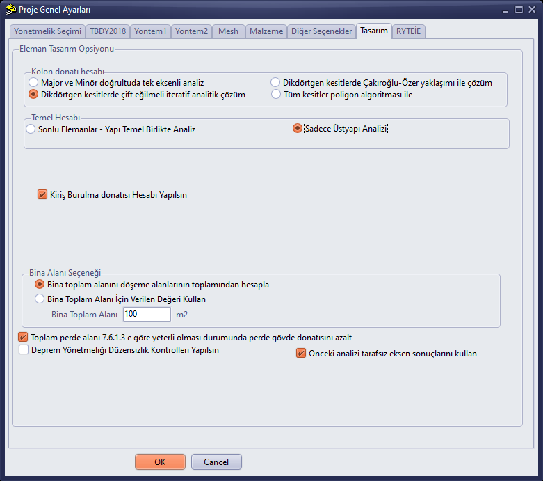
If you have modeled the foundation in the building, the finite elements – Superstructure-Foundation combined analysis option must be selected for reinforced concrete buildings. If no foundation model has been created, the superstructure only option must be selected so that columns and shear walls are assumed to be fixed at the base.