Creating a Grid Inside Selected Walls
A practical method with step-by-step instructions for creating grid elements (edge studs, intermediate studs, top chord beams, band beams, bottom chord beams) inside selected timber shear walls is presented below.
1-Model your wall plans in the project, taking into account doors and windows.

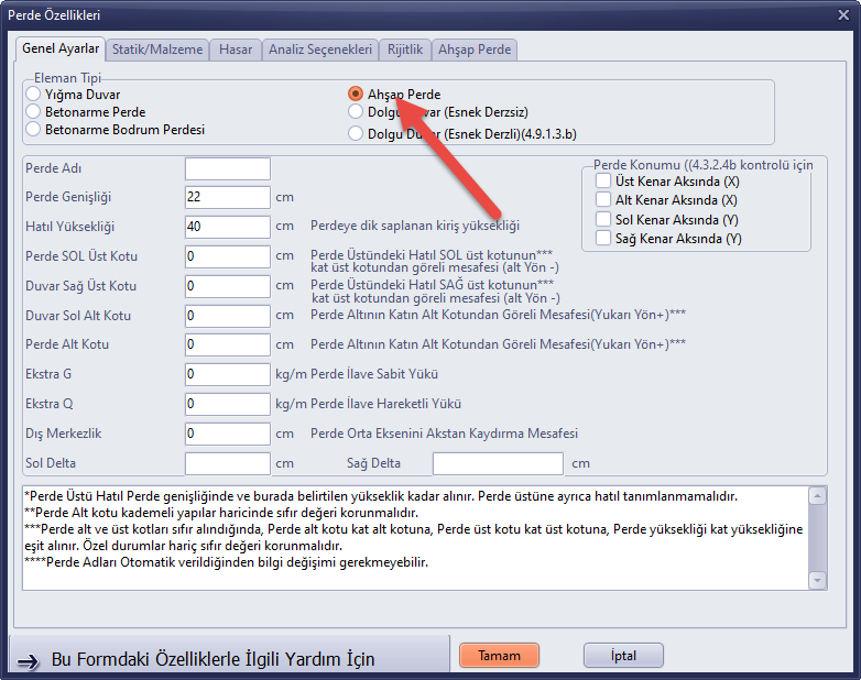
2-Select the wall elements in which you want to create a grid, then right-click and choose the option to change the properties of the selected walls. If the element type is not set to timber shear wall, check the timber shear wall option.
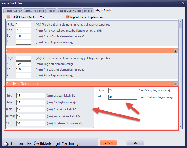
3-Go to the Timber Shear Wall tab and enter the stud and band beam parameters for the grid in the shear wall interior elements box.
4-While the walls to receive the grid are selected, click the "Create grid inside selected timber shear walls" option found under the Modify menu.

5-In the wall elements form that appears, make your adjustments. A DNM (Node Point Distance) value of 0 causes studs to be drawn flush to the left; a value of -10 cm for a 20 cm wide timber stud causes them to be drawn from the centre; and a DNM value of -20 for a 20 cm timber stud causes them to be drawn flush to the right. Having the "Create left stud" option checked while "Create right stud" is unchecked prevents edge studs from being drawn on top of each other in intersecting timber shear walls.

6-When the OK button is pressed, a form first appears to define the stud properties. In the form that opens, specify the properties and material of the studs. For detailed information about material assignment, see Defining Timber, Reinforced Concrete, Concrete, Steel, Masonry, and Other Materials in StatiCAD V6

7-A new form appears on screen for the properties of the beams to be created automatically. In the form that opens, specify the properties and material of the beams. For detailed information about material assignment, see Defining Timber, Reinforced Concrete, Concrete, Steel, Masonry, and Other Materials in StatiCAD V6

8-The wall grid elements (edge studs, intermediate studs, top chord beams, band beams) will then be created automatically. If the generated system is not as desired, you can use the Undo button to revert to the state before the command.

9-If there are points in the created elements that you wish to modify or edit, you can select the studs on the 2D modelling screen (main screen) and change them using the "Change properties of selected vertical bond beams" option. To change beam properties, you can select the beams in the three-dimensional view (3D Ultimate) as described at Editing Insufficient Elements in a Timber Building with StatiCAD and change them using the element properties button in the right-click menu.
10-If you are not satisfied with the generated grid and wish to recreate it, you will first need to delete the grid inside the wall. If you repeat the steps in this guide without deleting first, new elements will be created without removing the old ones. Therefore, the following method is practical for deleting the existing elements in the wall you wish to modify (recreate the grid).
10.1-Click button number 1 to enable selection by frame.
10.2 Select the elements you want to delete using the frame.
10.3 Remove beams above doors and windows from the selection group so you do not have to redraw them.
10.4 Click the filter button on the right side of the screen.
10.5 On the selection filter screen, keep the beam and vertical bond beam checkboxes checked to ensure the element types you want to delete remain selected. Uncheck the others and press the OK button.
10.6 Press the Delete button on screen or in the right-click menu.
10.7 To create a grid again inside the wall whose grid has been deleted, start from step 1 at the beginning of this article.


