Worked Example: Reinforced Concrete Building with Isolated Footings
1. About this article
This article explains, from start to finish and with screenshots of the program, how a three-storey reinforced concrete building is founded on isolated (pad) footings in StatiCAD: placing the footings under the columns, soil parameters, selecting the solution type, tie beams, analysis, automatic sizing of inadequate footings, the report, the foundation plan and the detail sheet. All checks of one footing (TT05) are recalculated by hand in Section 10, and the same building is compared with three solution types (classic, soil springs, shell + Winkler) in Section 11.
The inputs were entered through the interface; all numbers in the article are the results the program gave in this example. For details of commands and options: Isolated Footing Design, for the calculation basis: Theoretical Basis of Isolated Footings, for verification studies: Isolated Footing Verification Studies.
Version and files: Isolated footings are available in StatiCAD V.10.1.3.0 and later program versions, for all structure types. You can download the example files here (ZIP): TekilTemelOrnek_ilk.sy4 (building without footings), TekilTemelOrnek_temeller.sy4 (footings and tie beams entered, not sized), TekilTemelOrnek.sy4 (final design), TekilTemelOrnek_rapor.pdf (isolated footing report) and TekilTemelOrnek_temel_plani.dxf (foundation plan and details).
2. The example building
The building is a three-storey (storey height 3.0 m) reinforced concrete frame with a 15.0 × 9.0 m plan: 3 × 5.0 m spans in the X direction, 2 × 4.5 m spans in the Y direction, 12 columns (50 × 50 cm) on each storey, 30 × 50 cm beams and 12 cm slabs. There are no footings yet; in this article isolated footings will be placed under the storey 1 columns.
Table 1 – Model and earthquake data
| Quantity | Value |
|---|---|
| Material | C30 / B420C (including the footing; in the footing properties fck = fyk = 0 = project material) |
| Earthquake (TBDY 2018) | SS = 1.0; S1 = 0.28; ZC (Fs = 1.2; F1 = 1.5) → SDS = 1.20; SD1 = 0.42; I = 1; R = 8; D = 3 |
| Building mass | 364 t (three storeys) |
| Soil (footing properties) | qk = 420 kN/m² (qt = qk / 1.4 = 300 kN/m²); σem = 200 kN/m² (service); ks = 20,000 kN/m³; Df = 1.5 m; γn = 18 kN/m³; tanδ = 0.6 (default) |
| Foundation calculation | Classical (combined structure–foundation analysis off); isolated footing solution type: soil springs (Y) |
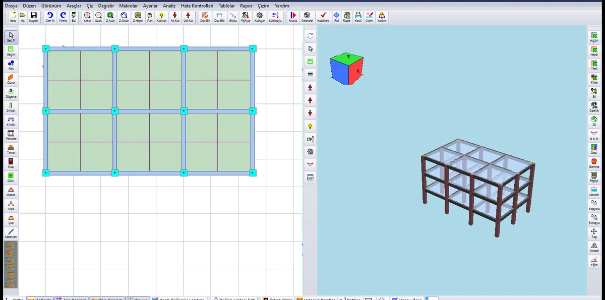
Figure 1 – Example building: ground floor plan (left) and 3D solid model (right)
3. Going down to the foundation level and placing the footings
- Go down to the FOUNDATION level with the Storey Down button on the toolbar ("Active Storey: FOUNDATION" in the status line). Isolated footings are drawn and selected only on the foundation level; the storey 1 columns appear on this level as grey lines.
- Open the Macros menu (Figure 2). The isolated footing commands are at the end of the menu: (1) Isolated Footing for Selected Columns, (2) Automatically Size Isolated Footings, (3) Tie Beams Between Isolated Footings, (4) Isolated Footing Project Solution.
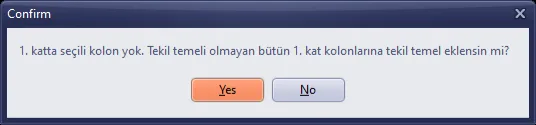
- Select Isolated Footing for Selected Columns. Because no column is selected, the program offers to add footings to all storey 1 columns that have none (Figure 3); confirm with Yes. 12 footings are added (Figure 4).
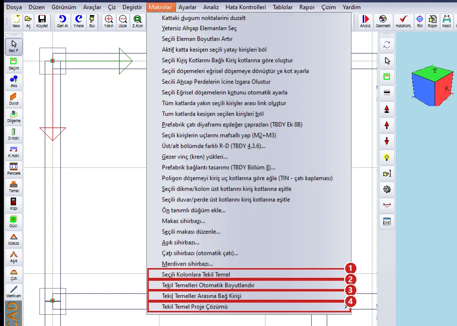
Figure 2 – Isolated footing commands of the Macros menu

The footings are placed at the column centre with the column angle; the default size is column + 100 cm sides (here 150 × 150 cm) and 50 cm thickness. Names are given as TT01, TT02, …; the label gives the name and Bx × By × H (Figure 5). To place them one by one, the Draw → Isolated Footing mode is used (clicking on a column, clicking on an empty area or dragging).
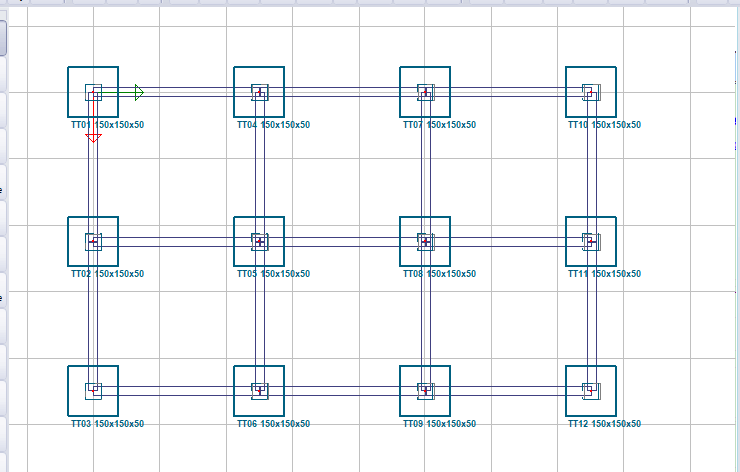
Figure 5 – 12 isolated footings on the foundation level (150 × 150 × 50 cm, dark cyan)
4. Footing properties
Select all footings (All on the right toolbar) and right-click on a footing. The menu has (1) Change Properties of Selected Isolated Footings (multiple edit) and (2) the properties window of the clicked footing itself (Figure 6).
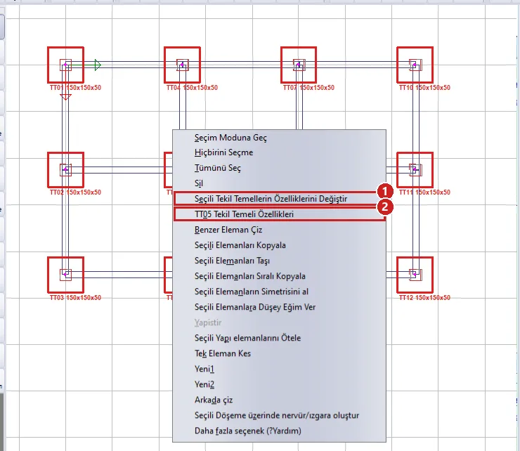
Figure 6 – Right-click menu: selected footings red
In the multiple edit window (Figure 7), fields left empty do not change; fields whose value is the same in all footings appear filled. (1) The dimensions stay at the default (automatic sizing will enlarge them). (2) Enter qk = 420, σem = 200, ks = 20,000, Df = 1.5 and γn = 18 in the soil fields. (3) The solution stays at "Project default"; the project default will be set to soil springs in Section 5. The drop-down list shows the options classic (K), soil springs (Y) and shell + Winkler (S).
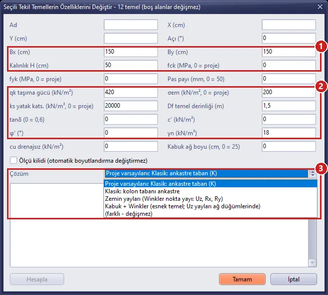
Figure 7 – Multiple properties window and the solution type list
Meaning of the fields: qk is the characteristic bearing capacity; the design bearing capacity is found as qt = qk / γRv (1.4), and qmax ≤ qt is checked in the load combinations. σem is checked only in the service (G+Q) combination. ks is used in the soil springs (Y) and shell (S) solutions. Df and γn give the weight of the backfill above the footing (backfill height Df − H). If qk = 0 is left and c′, φ′ are entered, the bearing capacity is computed with TBDY Eq. (16.8a).
5. Project solution: soil springs (Y)
From the Macros → Isolated Footing Project Solution submenu (Figure 8, (1)) Soil springs (Y) is selected (2). All footings whose solution field is "Project default" use this; the status line says "Isolated footing project solution: Soil springs (Y) (repeat the analysis)". In the Y solution the column base is not fixed: at the base node there are a vertical spring kz = ks·A and a rotational spring kθ = ks·I; horizontal displacements and torsion are restrained.
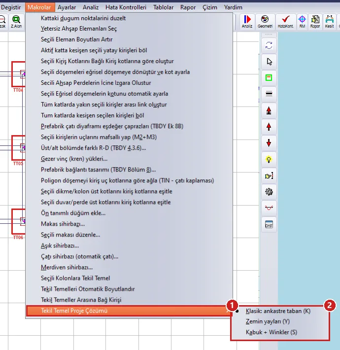
Figure 8 – Isolated Footing Project Solution submenu
6. Tie beams (TBDY 16.8.5)
TBDY 16.8.5 requires isolated footings to be connected with tie beams in two directions. Macros → Tie Beams Between Isolated Footings generates 30 × 50 cm tie beams between neighbouring footings: in this building 9 in the X direction, 8 in the Y direction, a total of 17 tie beams (Figure 10). Tie beams are drawn on the foundation level as strip footings of the type "Reinforced Concrete Tie Beam"; after the analysis they are designed with the axial force Nb = 0.10·SDS·Nk and the self-weight moments.

Figure 9 – Message of the tie beam macro
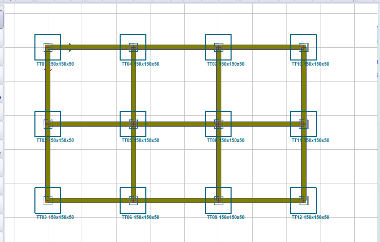
Figure 10 – Tie beams (olive green) and footings
Tie beams do not enter the analysis model: In the classical foundation calculation (combined structure–foundation analysis off), tie beams do not enter the finite element model; the column bases sit on the footing springs. Tie beams are only designed and drawn.
7. First analysis: inadequate footings
Open the analysis window with the Analysis button and click Start Analysis (79 s on this computer). At the end of the analysis all isolated footings and tie beams are designed automatically. All of the 150 × 150 × 50 cm footings are inadequate; the analysis warnings (Figure 11, (1)) list the inadequate checks for each footing:
- corner footings (TT01, TT03, TT10, TT12): soil (uplift), sliding 1.17, starter bar development, overturning / full uplift; in the earthquake combination the corner column takes tension and the footing base lifts completely,
- other footings: soil 1.26 – 1.34, starter bar development; a 50 cm thickness is not enough for the development length of the Ø14 column starter bars.
There is no warning in the tie beams. Inadequate footings are drawn orange on the plan (Figure 12).
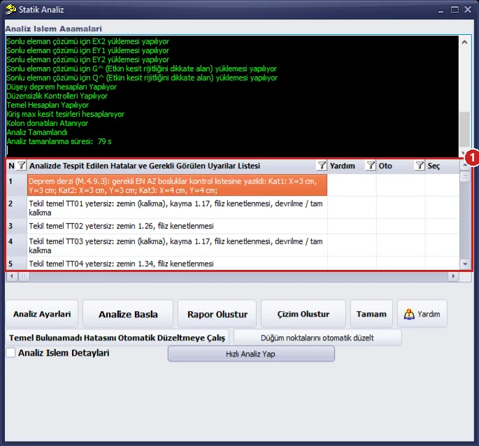
Figure 11 – First analysis: analysis steps and warning list
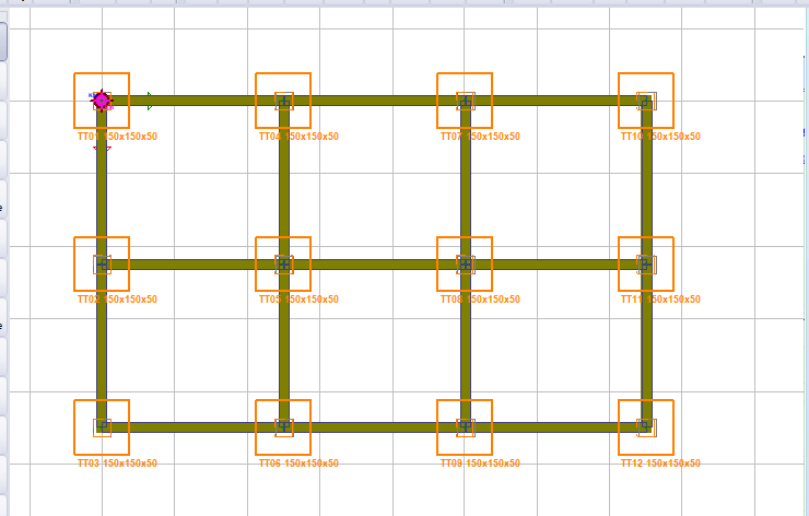
Figure 12 – Inadequate footings orange
To see the details of a footing, right-click it, open its own properties window and click Calculate (Figure 13, (2)). The window gives an instant design summary with the results of the last analysis, without saving (1): for TT05 soil ratio 1.29 (combination 23), sliding 0.49, shear 0.39, punching 0.18, bottom reinforcement 8 Ø16 / 195 mm in both directions; for Ø14 starter bars 484 mm development is required, and there is 418 mm in a 50 cm footing. Warnings are listed with explanations (here: the development length of the column starter bars does not fit into the footing thickness, TS 500 9.1).
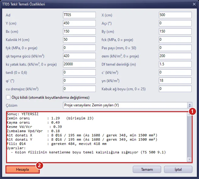
Figure 13 – Calculate in the TT05 properties window: INADEQUATE
8. Automatic sizing and the analysis loop
Macros → Automatically Size Isolated Footings brings the selected footings (all if there is no selection) to the smallest base and thickness with equal cantilevers using the forces of the last analysis: first the base is enlarged until soil pressure and sliding are satisfied, then the thickness until shear, punching, bending and starter bars are satisfied. The result is listed in a message box (Figure 15); the last line of the box reminds you to repeat the analysis.
Sizing time: At every trial size all load combinations (66 per footing in this example) are checked again with the partial contact solution; the smallest sufficient size is searched with exponential steps and halving. On this computer sizing the 12 footings took 17–31 seconds. During the operation the status line shows which footing is being sized (Figure 14).

Figure 14 – Status line during sizing
Sizing is done with the analysis forces; when the dimensions change the analysis must be repeated. This is especially important in the soil springs (Y) solution: as the footing grows, the rotational spring kθ = ks·B4/12 stiffens rapidly, the column base approaches fixity and the column attracts a larger base moment. In this example, in the analysis after the first sizing the corner footings were again inadequate (Figure 16): in the combination 0.9G + 0.3X + Y − 0.3Ez the corner column carries 10.7 kN tension and 80.7 kN·m moment, the eccentricity at the footing base is 1.02 m (half width 1.05 m), contact 4.6%, qmax = 1497 kN/m² (soil ratio 4.99). After the second sizing and analysis all footings are adequate (Figures 17 – 18).
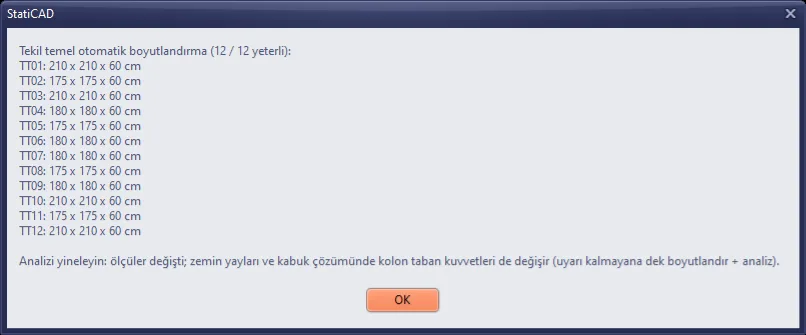
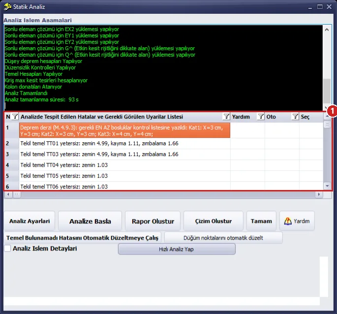
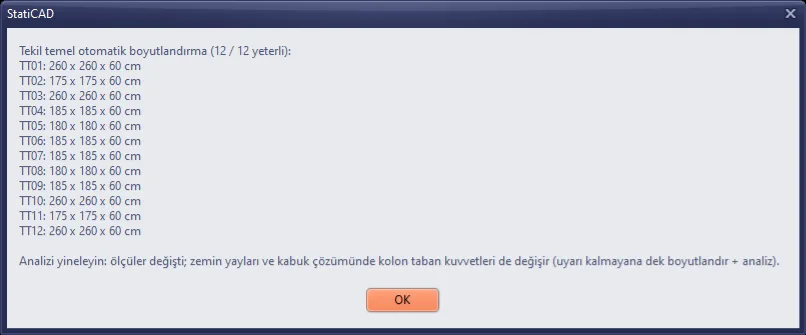
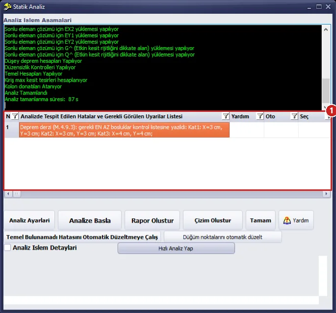
Table 2 – Sizing and analysis loop (Bx × By × H, cm)
| Step | Corner TT01, 03, 10, 12 | Edge (X) TT04, 06, 07, 09 | Edge (Y) TT02, 11 | Interior TT05, 08 | Analysis result |
|---|---|---|---|---|---|
| Macro (initial) | 150 × 150 × 50 | 150 × 150 × 50 | 150 × 150 × 50 | 150 × 150 × 50 | 12 footings inadequate (Section 7) |
| 1st sizing | 210 × 210 × 60 | 180 × 180 × 60 | 175 × 175 × 60 | 175 × 175 × 60 | corner: soil 4.99, sliding 1.11, punching 1.66; edge (X) and interior: soil 1.03; edge (Y) adequate |
| 2nd sizing | 260 × 260 × 60 | 185 × 185 × 60 | 175 × 175 × 60 | 180 × 180 × 60 | all footings adequate |
Convergence: In the classic (K) solution the column base forces do not depend on the footing size, so a single sizing is enough (only the footing weight changes). In the Y and S solutions repeat the "size → analyse" loop until no warning remains; in this example two rounds were enough. Tick the Size lock on a footing whose size you want to keep.
9. Final design
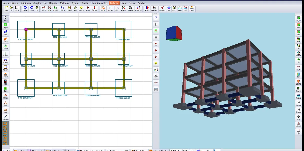
Figure 19 – Final design: all footings adequate (3D solid model on the right, from below)
Table 3 – Isolated footing design summary (most unfavourable of the combinations; ratio = demand / capacity)
| Footings | Size (cm) | Soil | Sliding | Shear | Punching | Bottom reinforcement (x = y) | Top reinforcement | Ring bar |
|---|---|---|---|---|---|---|---|---|
| TT01, TT03, TT10, TT12 | 260 × 260 × 60 | 0.69 | 0.90 | 0.31 | 0.72 | 13 Ø18 / 21 | 11 Ø14 / 25 | Ø18 |
| TT04, TT06, TT07, TT09 | 185 × 185 × 60 | 0.94 | 0.61 | 0.30 | 0.14 | 9 Ø18 / 22 | 8 Ø14 / 25 | Ø18 |
| TT02, TT11 | 175 × 175 × 60 | 0.88 | 0.61 | 0.24 | 0.10 | 11 Ø16 / 16 | 8 Ø14 / 23 | Ø16 |
| TT05, TT08 | 180 × 180 × 60 | 0.95 | 0.41 | 0.29 | 0.14 | 9 Ø18 / 21 | — | Ø18 |
Top reinforcement is provided because in some earthquake combinations the top face of the footing is in tension (in the uplifted region the weight of the footing and backfill bends the cantilever downwards). All 17 tie beams are 30 × 50 cm, 4 Ø12 top and 4 Ø12 bottom, stirrups Ø8/20 (Nk = 485 – 569 kN, Nb = 0.10·1.20·Nk = 58 – 68 kN). In the final analysis the periods are Tx = 0.394 s, Ty = 0.416 s, and the base shear forces are Vtx = 476.4 kN, Vty = 450.6 kN.
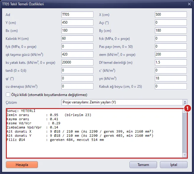
Figure 20 – Calculate in the TT05 properties window: ADEQUATE
10. Hand verification for TT05
The report values for the interior footing TT05 (180 × 180 × 60 cm, column DHB05 50 × 50 cm at the footing centre) were recalculated by hand. A = 1.8² = 3.24 m², dx = 541 mm, dy = 523 mm (cover 50 mm), fcd = 20.0 MPa, fctd = 1.267 MPa, fyd = 365.2 MPa.
10.1 Weights and soil springs
Footing Wf = 25 · 3.24 · 0.60 = 48.6 kN; backfill Wd = 18 · (1.50 − 0.60) · (3.24 − 0.25) = 48.4 kN; total 97.0 kN. Y springs: kz = ks·A = 20,000 · 3.24 = 64,800 kN/m; kθ = ks·B4/12 = 20,000 · 1.84/12 = 17,496 kN·m/rad (same as the report).
10.2 Soil pressure
Service G+Q: Nt = 487.0 kN, ex = −1.0 cm → q = 487.0 / 3.24 · (1 ± 6 · 0.010 / 1.8) = 150.3 · (1 ± 0.033) = 155.2 / 145.4 kN/m²; 155.2 / σem = 155.2 / 200 = 0.78.
Governing earthquake combination G + nQ + 0.2S − X1 − 0.3Y2 + 0.3Ez (earthquake effects magnified by max(1; 0.6D) = 1.8 according to TBDY 4.10.3): Nt = 546.2 kN, ex = −15.86 cm, ey = −4.86 cm. Since |ex|/B + |ey|/B = 0.088 + 0.027 = 0.115 ≤ 1/6, the base is in full contact:
q = Nt/A · (1 ± 6ex/Bx ± 6ey/By) = 168.6 · (1 ± 0.529 ± 0.162) → qmax = 285.0 kN/m², qmin = 52.2 kN/m²
qt = 420 / 1.4 = 300 kN/m² → soil ratio 285.0 / 300 = 0.95 (report: 0.95).
10.3 Punching shear (TS 500 8.3.1)
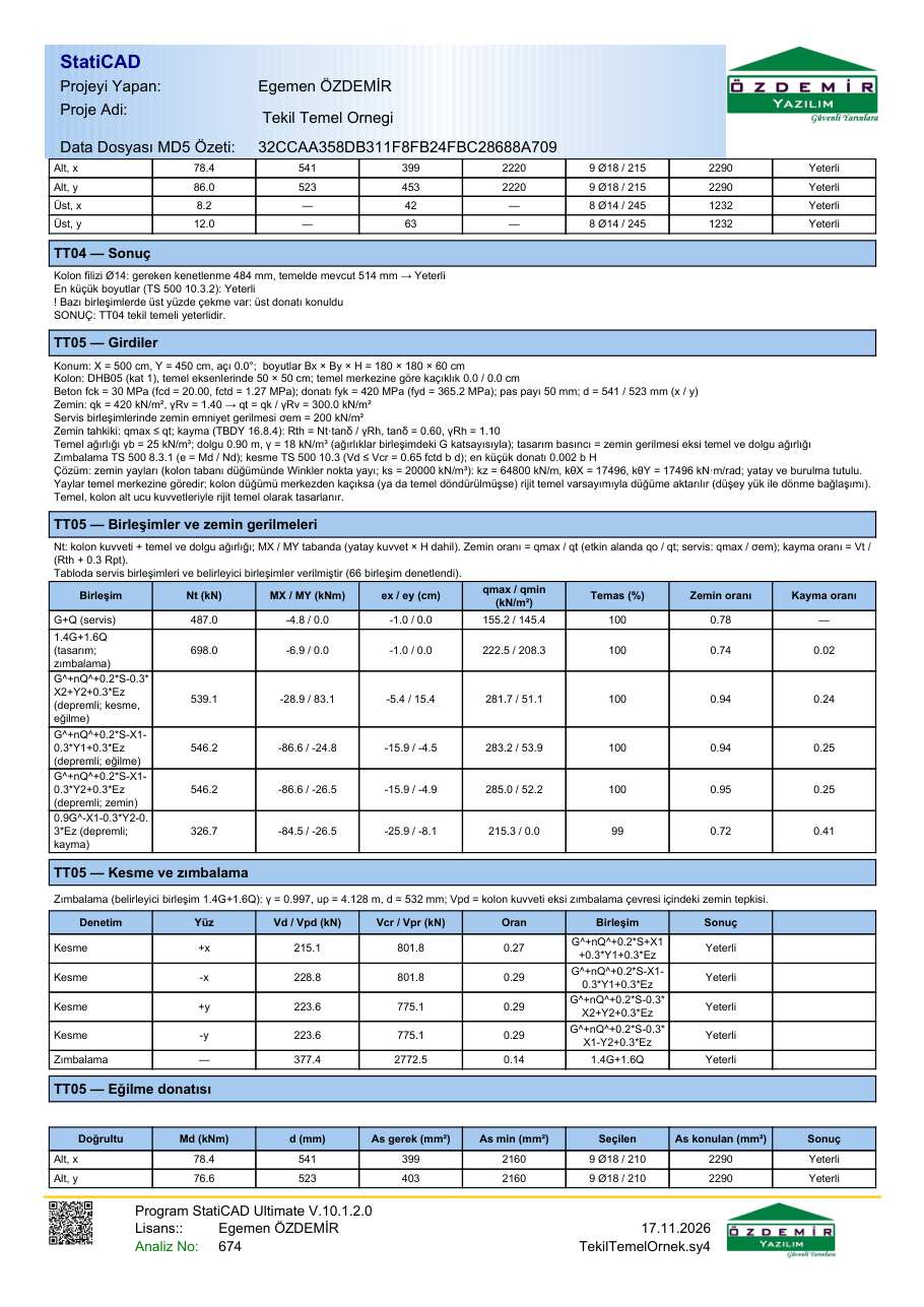
1.4G + 1.6Q: Nt = 698.0 kN → column force Nd = 698.0 − 1.4 · 97.0 = 562.2 kN; design pressure (weight deducted) 562.2 / 3.24 = 173.5 kN/m². d = (541 + 523)/2 = 532 mm; punching perimeter side 0.50 + 0.532 = 1.032 m, up = 4.128 m, inner area 1.065 m². Vpd = 562.2 − 173.5 · 1.065 = 377.4 kN; Vpr = γ·fctd·up·d = 0.997 · 1.267 · 4128 · 532 / 1000 = 2772 kN; ratio 0.14 (report: 377.4 / 2772.5).
10.4 Shear and bending (TS 500 10.3)
Vcr = 0.65·fctd·b·d = 0.65 · 1.267 · 1800 · 541 / 1000 = 801.8 kN; on the −x face Vd = 228.8 kN → 0.29. In the x direction Md = 78.4 kN·m: for As = 400 mm² the compression block a = 400 · 365.2 / (0.85 · 20 · 1800) = 4.8 mm, As = Md / (fyd·(d − a/2)) = 78.4·106 / (365.2 · 538.6) = 399 mm²; the minimum reinforcement 0.002·b·H = 0.002 · 1800 · 600 = 2160 mm² governs; 9 Ø18 = 2290 mm² (spacing 210 mm).
10.5 Column starter bars (TS 500 9.1)
lb = 0.12·(fyd/fctd)·ϕ = 0.12 · (365.2 / 1.267) · 14 = 484 mm; the available length in the footing is 600 − 50 − 18 − 18 = 514 mm → adequate. With a 50 cm thickness the available length was 418 mm (Section 7).
Report page: The same values are on the TT05 page of the report (Section 12, Figure 24).
11. Comparison of solution types (K / Y / S)
With the final dimensions, the building was analysed again with the solution field of the footings set in turn to Classic (K), Soil springs (Y) and Shell + Winkler (S) (Table 4). The footing dimensions and soil parameters are the same in all three solutions.
Table 4 – K / Y / S with the same footing dimensions
| Quantity | K (fixed base) | Y (soil springs) | S (shell + Winkler) |
|---|---|---|---|
| Tx / Ty (s) | 0.291 / 0.295 | 0.394 / 0.416 | 0.394 / 0.416 |
| Vtx / Vty (kN) | 598.3 / 594.1 | 476.4 / 450.6 | 476.4 / 450.6 |
| Inadequate isolated footings | 12 (soil: overturning / full uplift, 2.60 in the interior footing) | 0 | 0 |
| TT01 soil / sliding / punching | overturning / 0.94 / 0.25 | 0.69 / 0.90 / 0.72 | 0.69 / 0.86 / 0.25 |
| TT05 soil / sliding / punching | 2.60 / 0.51 / 0.25 | 0.95 / 0.41 / 0.14 | 0.96 / 0.40 / 0.14 |
| TT05 Md x / y (kN·m) | 153.7 / 157.6 | 78.4 / 76.6 | 79.7 / 77.8 |
- K takes the column base as fixed: the structure is stiffer (periods 26–29% shorter), the base shear is 26–32% larger and the column base moments are about twice as large. Footings sized for Y are inadequate in K; if K is to be selected, the footings must be sized with the K results.
- In Y, footing rotation reduces the base moments and lengthens the periods. kθ ≈ 17,500 kN·m/rad is less than a tenth of the bending stiffness (4EI/L) of the 50 × 50 column; the column base is closer to pinned than to fixed.
- In S the modal analysis is done with Y springs (the periods are the same); static load cases are solved with the shell mesh at the footing base. Soil, sliding, shear and bending are the same as Y within 1–4%; the punching ratio of the corner footing, however, drops from 0.72 to 0.25: in a flexible footing the pressure concentrates around the column and the soil reaction inside the punching perimeter increases. In Y and K, with the rigid footing assumption, the pressure gathers at the edge at large eccentricity.
The solution type also affects the superstructure: The solution type changes not only the footing but also the earthquake forces of the superstructure. If the modulus of subgrade reaction is uncertain, compare the two solutions; the selection and the soil parameters are the responsibility of the project's responsible engineer.
12. Calculation report
Open the Report Selection window with the Report button, clear the selection with Deselect All, tick the Isolated Footing Calculation Report (TS 500, TBDY 2018) node (Figure 21, (1)) and click Generate All Selected Reports (2). The report opens in the preview (15 pages); it can be printed or saved as PDF.
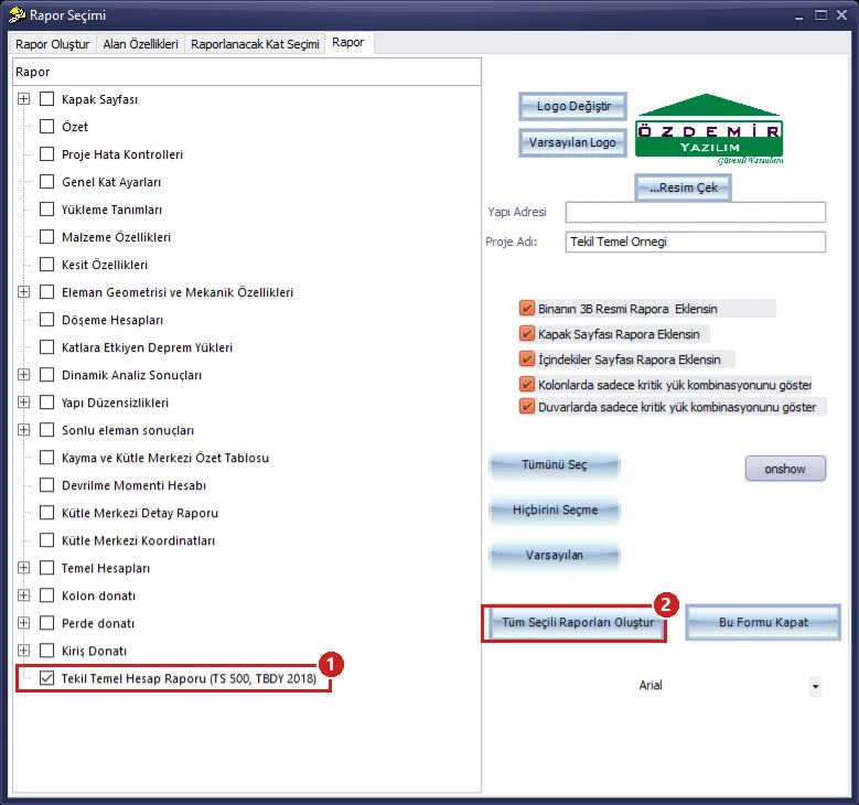
Figure 21 – Report Selection: Isolated Footing Calculation Report node
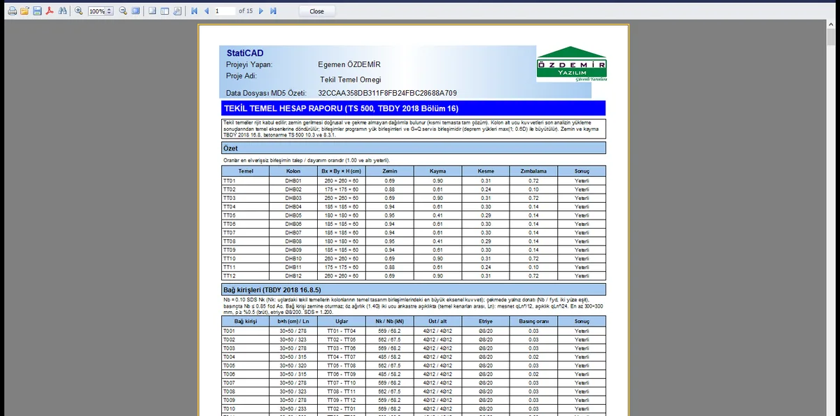
Figure 22 – Report preview: summary table
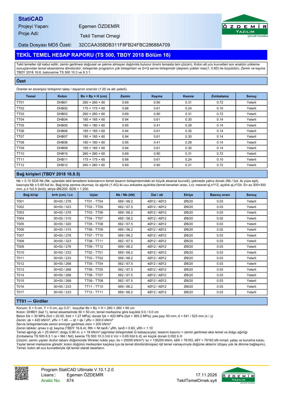
The report contains a summary table, a tie beams block and, for each footing, the blocks Inputs (geometry, material, soil, solution type and springs), Combinations and soil pressures (service and governing combinations), Shear and punching, Flexural reinforcement and Result.
13. Foundation plan and detail sheet
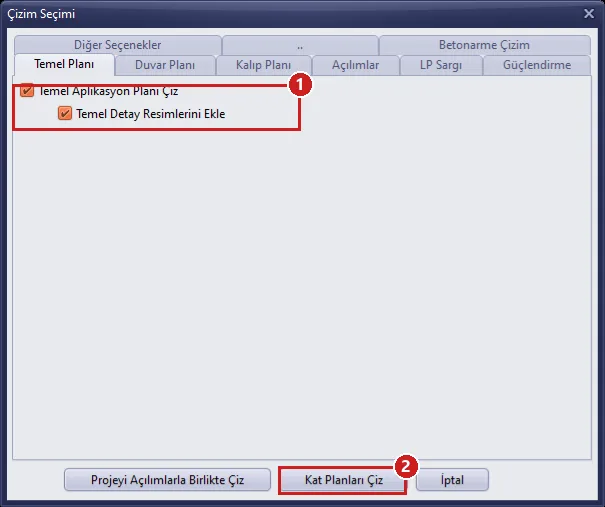
Open the Drawing Selection window with the Drawing button. In the Foundation Plan tab, Draw Foundation Setting-Out Plan and Add Foundation Detail Drawings must be ticked (Figure 25, (1)); Draw Storey Plans (2) draws the foundation plan, the details and the storey formwork plans into the CivilDraw window (Figure 26).
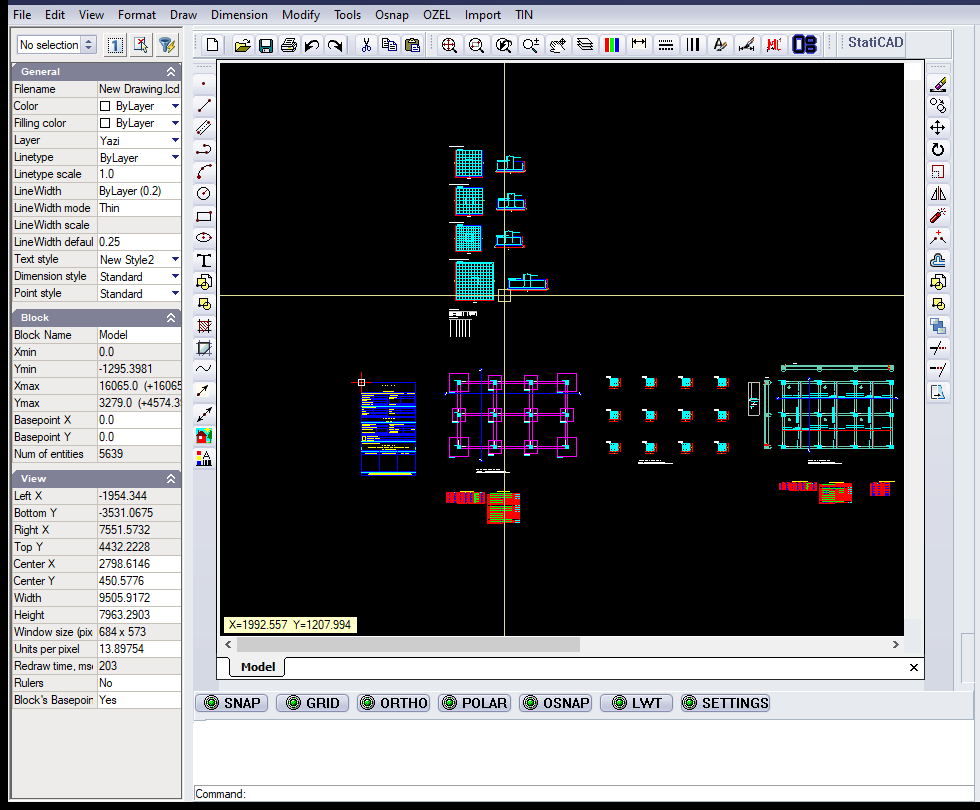
The foundation plan contains the isolated footings, tie beams, columns, axis and section marks, footing names and dimensions (Figure 27). In the detail sheet, footings with the same dimensions and reinforcement are grouped in a single detail: for each group a plan (bottom reinforcement grid) and section A-A (thickness, blinding concrete, bottom and top reinforcement, ring bar, column starter bars) are drawn (Figure 28). The isolated footing table and the tie beam table (Figure 29) and the sheet reinforcement quantity (Figure 30) are added to the sheet.
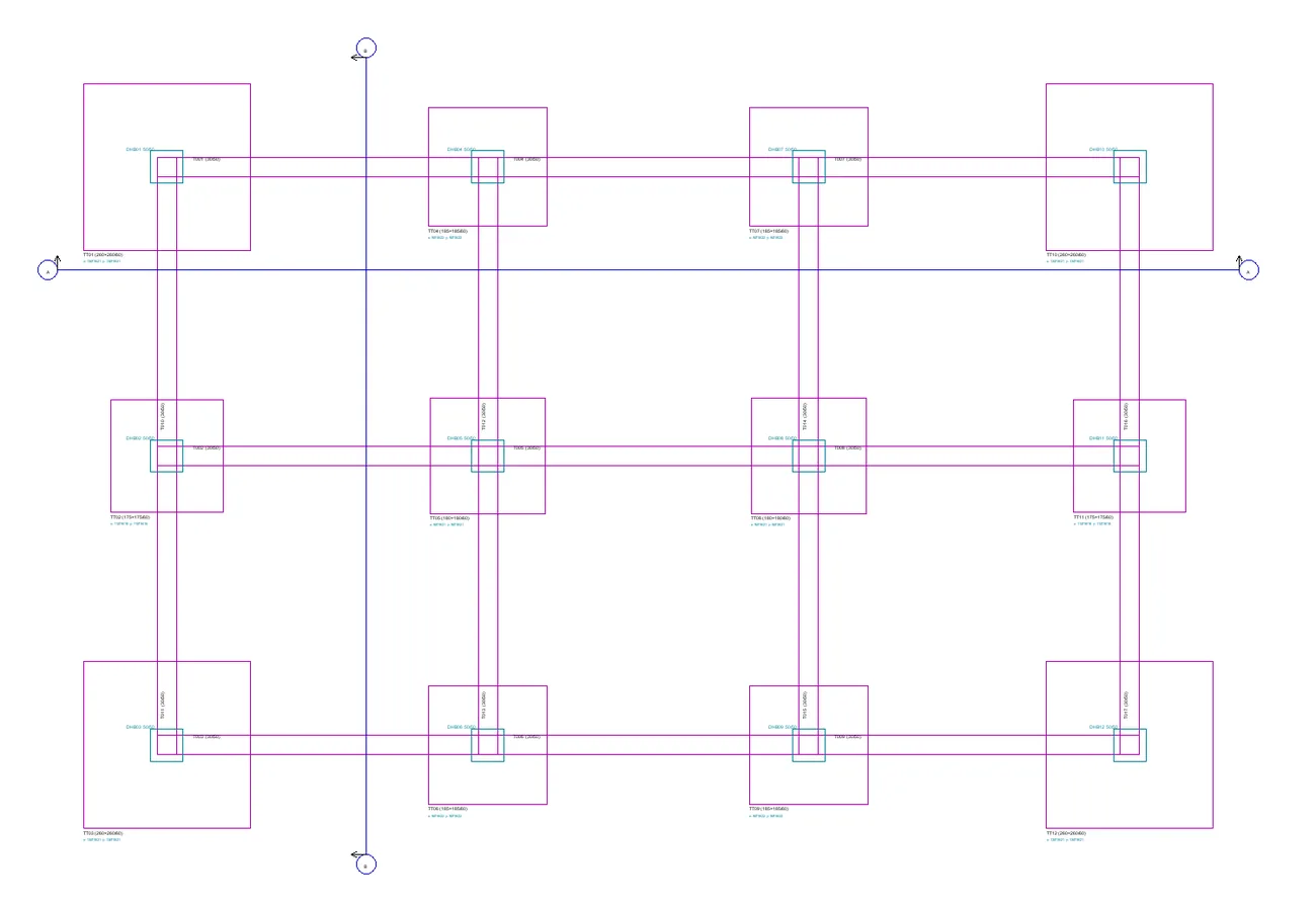
Figure 27 – Foundation setting-out plan (from the DXF output)
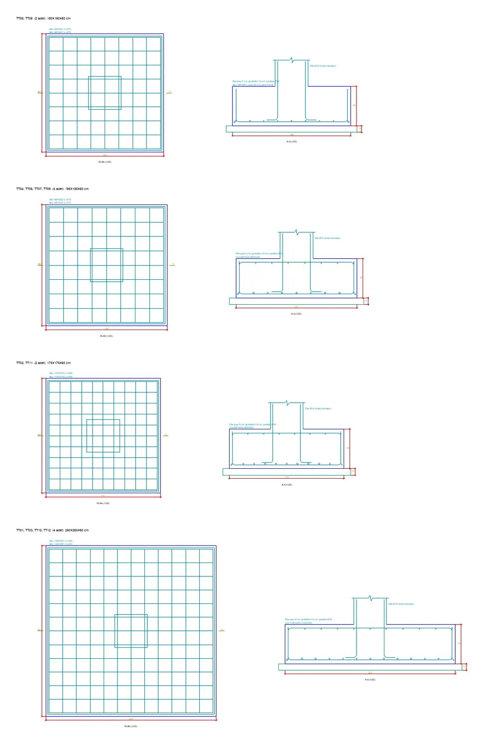
Figure 28 – Isolated footing details: four footing groups, plan and section A-A
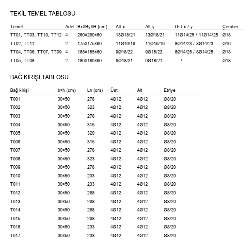
Figure 29 – Isolated footing table and tie beam table
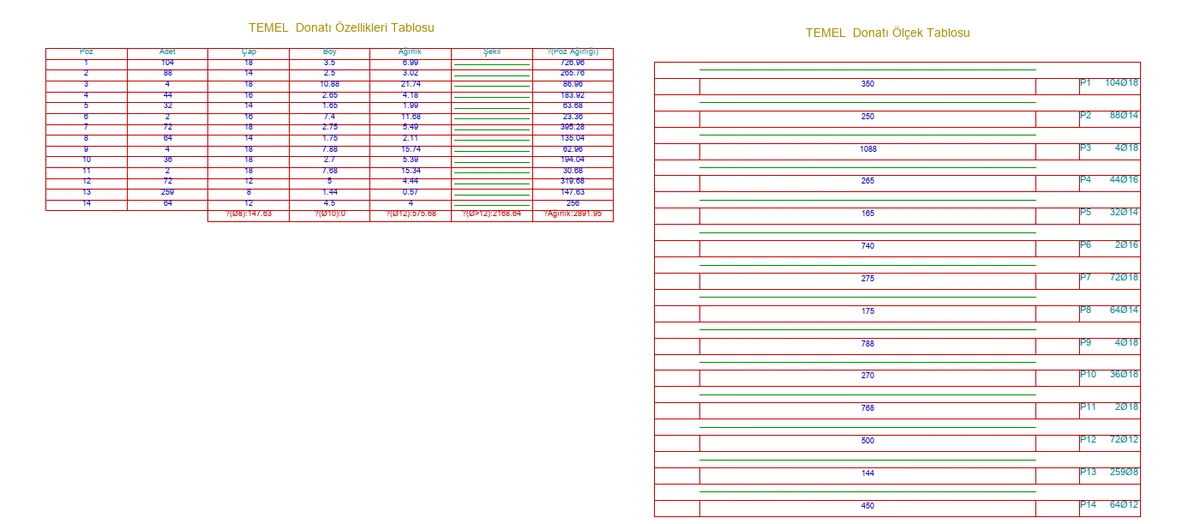
Figure 30 – Foundation reinforcement properties and scale tables (sheet quantity)
Quantity take-off: In the quantity report the concrete, formwork and blinding concrete of the isolated footings and tie beams are added to the grand totals with the "Isolated Footings" and "Tie Beams" lines; their reinforcement enters the sheet reinforcement quantity (Figure 30).
14. Reinforcement diameters and 3D view
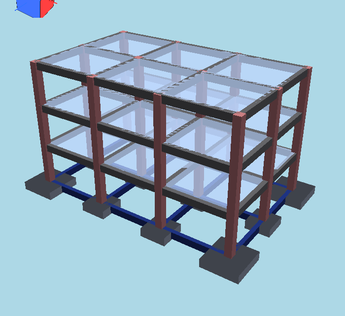
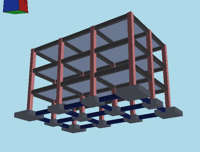
Footing reinforcement is selected from the diameters in the Isolated Footing tab of the Tables → Reinforcement Selection window (Figure 31; default Ø14, Ø16, Ø18). You can change the diameters here and repeat the analysis. Isolated footings and tie beams are also drawn in the 3D solid model (Figures 32 – 33); in the 3D window they can be selected by clicking or by window and the properties window can be opened.
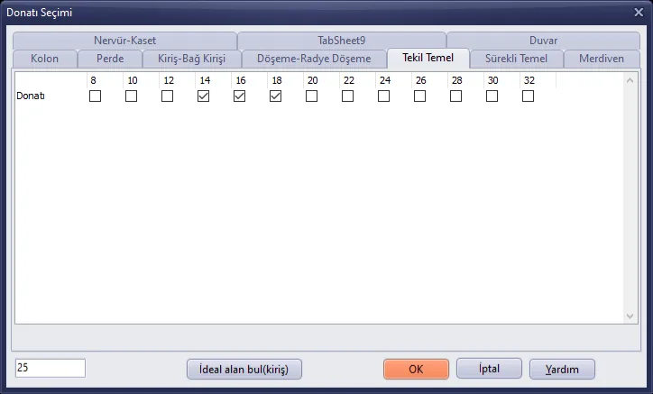
Figure 31 – Reinforcement Selection: Isolated Footing tab
15. Points to note
- As the footing dimensions change (especially in the Y and S solutions) the column base forces change; repeat the analysis after sizing and continue the loop until no warning remains (Section 8).
- Corner columns can take tension in earthquake combinations; combinations containing 0.9G − 0.3Ez govern uplift and overturning in the corner footing. Top reinforcement may be required in these footings.
- The footing thickness must at least provide the development length of the column starter bars (in this example 484 mm for Ø14 → H ≥ 60 cm).
- In the classical foundation calculation tie beams do not enter the analysis model; if you use isolated footings together with a strip footing, select the combined structure–foundation analysis (Isolated Footing Design Section 14).
- Automatic sizing does not touch footings with the size lock ticked; if the total base area exceeds half the building area, a raft is recommended.