Isolated Footing Design
This article explains drawing and editing isolated (pad) footings in StatiCAD, how they are represented in the analysis (the K / Y / S solution types), their design, tie beams, the report, drawing and quantity take-off. An isolated footing can be used under the first-storey columns in every structure type (reinforced concrete, masonry, steel, timber, precast). For the calculation basis see Theoretical Basis of Isolated Footings, and for verification studies see Isolated Footing Verification Studies.
Scope: a flat (without socket) isolated footing with a single column and a rectangular base. Precast socket (pocket) footings and footings with several columns (combined) are outside this scope. Isolated footings are available in StatiCAD V.10.1.3.0 and later program versions.
1. General flow
- Enter the columns and the superstructure as usual.
- Go down to the FOUNDATION storey (storey down button). Isolated footings are drawn and selected only on the foundation level.
- Place the footings: one by one with Draw → Isolated Footing, or in bulk with Macros → Isolated Footing for Selected Columns (Sections 2–3).
- If necessary, enter the footing properties (dimensions, material, soil, solution type) in the properties window (Section 5).
- Run the analysis. At the end of the analysis all isolated footings and tie beams are designed automatically; inadequate ones are listed in the analysis warnings and drawn orange on the plan (Section 7).
- If you wish, enlarge the dimensions according to the analysis result with Macros → Automatically Size Isolated Footings and repeat the analysis.
- Obtain the report (the Isolated Footings node), the foundation plan, the detail sheet and the quantity take-off (Sections 9–10).
An end-to-end example in which all steps are explained with screenshots (a three-storey reinforced concrete building, 12 isolated footings, tie beams, sizing loop, hand verification, K / Y / S comparison, report and drawings): Worked Example: Reinforced Concrete Building with Isolated Footings.
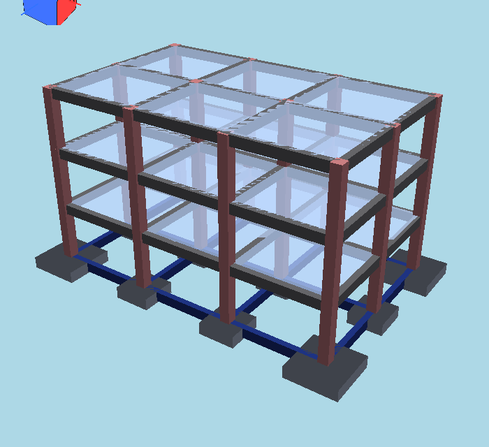
Figure 1 – Isolated footings and tie beams in the example building (3D solid model)
2. Drawing an isolated footing
Draw → Isolated Footing opens the placement mode (only on the foundation level; if you are on another storey it gives a warning). The mode stays on; a right-click ends it.
| Action | Result |
|---|---|
| Left-click inside the section of a first-storey column | A footing at the column centre, with the column angle: sides column + 100 cm (at least 100 cm), thickness 50 cm. If that column already has a footing, none is added. |
| Click on an empty area | A 150 × 150 × 50 cm footing at the clicked point. |
| Drag and drop on an empty area | A footing the size of the dragged rectangle (if both sides are at least 20 cm); the dimension appears in the status line during dragging. |
| Right-click | Exits the mode. |
Footing names are given automatically (TT01, TT02, …). The column matching is geometric: if the centre of the first-storey column falls inside the footing base, the footing belongs to that column. A footing without a column can be drawn (its label says "no column") but it does not enter the analysis.
3. Macros
| Command | Description |
|---|---|
| Isolated Footing for Selected Columns | Adds footings with the default size under the selected first-storey columns (if there is no selection, under all first-storey columns that have no footing). |
| Automatically Size Isolated Footings | Brings the selected (if none, all) footings to the smallest base and thickness with equal cantilevers, using the last analysis result. Footings with the size lock ticked are skipped. If the total base area exceeds half the building area, the hint "a raft may be more suitable" is given. Sizing is done with the rigid footing pressure; because the dimensions change, repeat the analysis. During sizing the status line shows the footing being sized and its sequence number (under half a minute for 12 footings). The result box reminds you to repeat the analysis: in the soil springs (Y) and shell (S) solutions the column base forces also change when the dimensions change; continue the sizing + analysis loop until no warning remains. |
| Tie Beams Between Isolated Footings | Generates 30 × 50 cm tie beams between neighbouring footings (on the foundation level, type "Reinforced Concrete Tie Beam"); skips pairs that are already connected (Section 8). |
| Isolated Footing Project Solution | The type that footings with the solution type "Project default" will use: Classic (K), Soil springs (Y), Shell + Winkler (S). Section 6. |
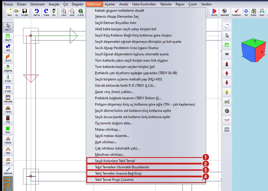
Figure 2 – Macros menu: (1) Isolated Footing for Selected Columns, (2) Automatic Sizing, (3) Tie Beam, (4) Project Solution
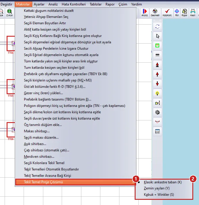
Figure 3 – Isolated Footing Project Solution submenu
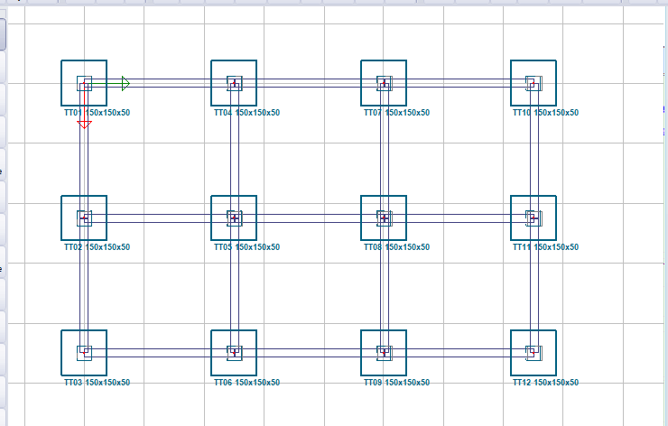
Figure 4 – Footings added by the macro (150 × 150 × 50 cm), name and size on the labels
4. Selection and editing
- Selection: left-click (toggles), window selection (a window drawn from the right also selects whatever it crosses), right-click (if no footing is selected, selects the clicked one and opens the menu), select all / clear selection.
- Delete, Copy, Move, Sequential Copy, Mirror: the same commands as for other members apply to the selected footings.
- Rotate (Z axis): the position and angle of the selected footings rotate. Shift: translated by dx, dy (level shift is not applied to the footing).
- Find Object: finds, selects and zooms to a footing by its name (e.g. TT03).
- Selection Filter: if the "Footing" box is switched off, isolated footings are also excluded from selection.
- Selection Groups: selected footings are added to the group, and when the group is selected the footings are selected too; membership is saved to the file.
- Undo: all footing operations can be undone.
- Storey 1 plan: the outline of isolated footings appears dashed grey on storey 1 (display only).
Colours on the plan: dark cyan normal, red selected, orange inadequate in the last analysis. The column trace is drawn dashed; the label gives the name and Bx × By × H.
5. Properties window
Select the footing and open it from the right-click menu or with the Properties command. If several footings are selected, the multiple edit window opens: fields left empty do not change, fields with different values appear empty.
| Field | Unit | Description |
|---|---|---|
| Name, X, Y, Angle | cm, ° | Footing centre and the angle of the local x axis. |
| Bx, By, H | cm | Base dimensions and thickness. |
| fck, fyk | MPa | 0 = project foundation material. |
| Cover | mm | Net concrete cover; 0 = 50 mm (TS 500 10.1). |
| qk | kN/m² | Characteristic bearing capacity. If 0, it is computed from c′ and φ′, if given, with TBDY Eq. 16.8a. |
| σem | kN/m² | Service (G+Q) allowable soil pressure; 0 = project allowable soil pressure. |
| ks | kN/m³ | Modulus of subgrade reaction (Y and S solutions); 0 = project modulus of subgrade reaction. |
| Df, tanδ, c′, φ′, γn, cu | m, —, kN/m², °, kN/m³, kN/m² | Footing depth and soil parameters (bearing capacity, sliding). tanδ 0 = 0.6. If cu is given, undrained sliding. |
| Shell mesh size | cm | Shell mesh size in the S solution; 0 = 25 cm. |
| Size lock | — | Automatic sizing does not change it. |
| Solution | — | Project default / Classic / Soil springs / Shell + Winkler (Section 6). |
The Calculate button shows an instant design summary with the last analysis results (without saving).
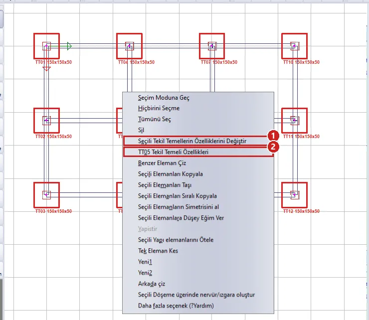
Figure 5 – Right-click menu: (1) multiple properties of the selected footings, (2) properties of the clicked footing
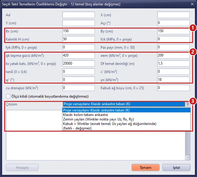
Figure 6 – Multiple properties window: (1) dimensions, (2) soil parameters, (3) solution type
6. Solution types: K, Y, S
The solution type determines how the footing is represented in the analysis model and where the soil pressure in the design is taken from.
| K — Classic | Y — Soil springs | S — Shell + Winkler | |
|---|---|---|---|
| Column base | Fixed | Springs at the column base node: kz = ks·A, kθ = ks·I (about the footing centre; if the node is eccentric, transferred to the node with a rigid footing); horizontal and torsion restrained | Footing base is a shell mesh; at each node a vertical spring ks × tributary area; the column projection is a rigid zone |
| Footing rotation | None | Yes (rigid footing) | Yes (flexible footing) |
| Soil pressure in the design | Rigid, linear | Rigid, linear | Shell node pressures (actual distribution) |
| Speed | Fastest | Fast | Hundreds of nodes per footing |
- K on firm ground and when results consistent with the usual hand calculation are wanted. Fixity can enlarge the base moments.
- Y to see the effect of footing rotation on the superstructure. Base moments and the structure period approach reality.
- S for the most realistic pressure distribution in thin or wide footings, on weak ground and when the column is not at the footing centre. The pressure concentrates under the column; section moments, shear and punching are computed from this distribution. Because footings of usual proportions behave almost rigidly, the S and Y results are mostly close.
In the S solution, in the FEM modal (period) calculation the footing is represented by rigid equivalent Y springs; static load cases are solved with the shell. The soil does not take tension: if part of the base remains in tension in the linear solution of a combination, the footing is solved again for that combination by removing the springs working in tension in the same mesh (compression-only). The pressure is zero in the uplifted region and increases in the remaining region; soil pressure, section moments, shear and punching are computed from this distribution. The report gives the number of combinations solved again and the smallest contact ratio. Combination forces come from the linear analysis (redistribution of the superstructure is not taken).
If the column is drawn eccentric (for example placed from its edge), in the FEM the column force acts at the FEM node. The design takes this into account in every solution type: moments are moved to the section centre (M′ = M + N·e) and the eccentricity is written in the report. In the Y solution the springs are also set up about the footing centre and transferred to the node: the spring at the node is a full matrix coupling vertical load and footing rotation (Theoretical Basis of Isolated Footings Section 4).
7. Analysis and design
At the end of the analysis each isolated footing is designed with the forces at the lower end of the first-storey column and the project load combinations:
- Combinations: every load combination in the project + service G+Q (allowable soil pressure check). In footing design the horizontal earthquake load cases are magnified by max(1; 0.6·D) according to TBDY 4.10.3 (D in a light steel building).
- Footing and backfill weight are added with the G factor of the combination.
- Checks: soil pressure (qmax ≤ qt, service qmax ≤ σem), sliding (TBDY 16.8.4), overturning, minimum dimensions (TS 500 10.3.2), shear (TS 500 10.3), punching shear (TS 500 8.3.1), flexural reinforcement and minimum reinforcement, development of column starter bars (TS 500 9.1).
- Bar diameters are selected from the candidates in the Isolated Footing tab of the Reinforcement Selection window.
- Footings that cannot be designed or are inadequate are listed in the analysis warnings; they appear orange on the plan.
- If strip footings and isolated footings are used together (mixed foundation) and Foundation Calculation is set to classical, the analysis gives a warning: in this solution the columns on the strip footing are taken fixed at the base, and the earthquake forces of the isolated footings may remain low (Section 14).
- In columns with footings, the column bottom starter height is adjusted according to the footing thickness.
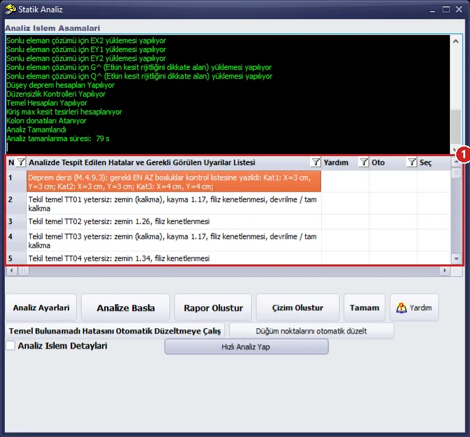
Figure 7 – Inadequate isolated footings in the analysis warnings (1)
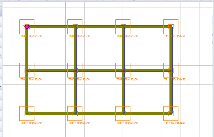
Figure 8 – Inadequate footings orange on the plan
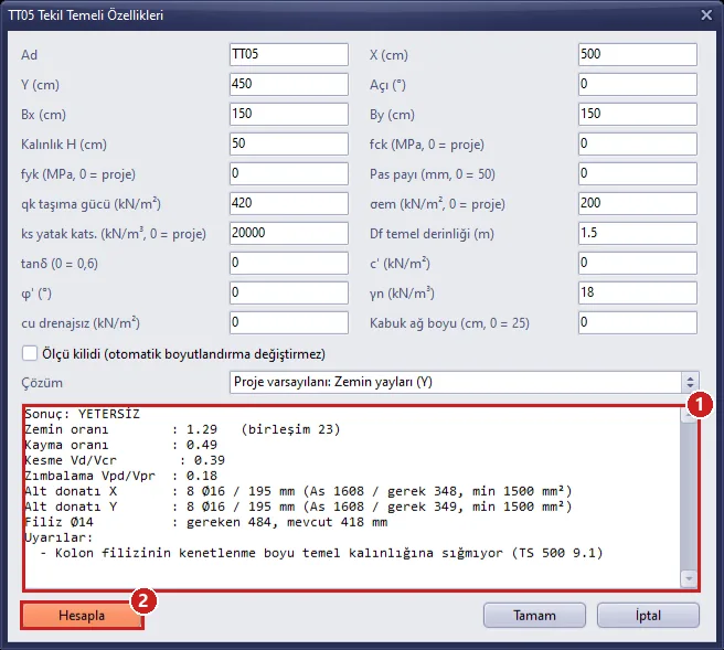
Figure 9 – Calculate in the properties window (2): instant design summary with the last analysis (1)
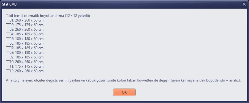
Figure 10 – Automatic sizing result
8. Tie beams (TBDY 16.8.5)
According to TBDY 16.8.5, isolated footings must be connected with tie beams in two directions (not required on ZA soil). Macros → Tie Beams Between Isolated Footings generates tie beams between neighbouring footings; you can also draw them by hand as strip footings on the foundation level and select the type Reinforced Concrete Tie Beam. At the end of the analysis the tie beams are designed with the axial force Nb = 0.10·SDS·Nk and the self-weight moments; directions without a tie beam are reported as warnings. In the classical solution tie beams do not enter the FEM model.
In the combined structure–foundation (finite element) analysis, tie beams and strip footings enter the model. The nodes that fall inside the base outline of an isolated footing are tied to the footing with a rigid link (even if it is drawn from the column edge) and the soil springs of these nodes are removed; the isolated footing represents the soil. The footing is designed with the total load coming from the column and the connected members: N, MX and MY are taken from the total finite element reaction of the footing. The report gives this information for a connected footing.
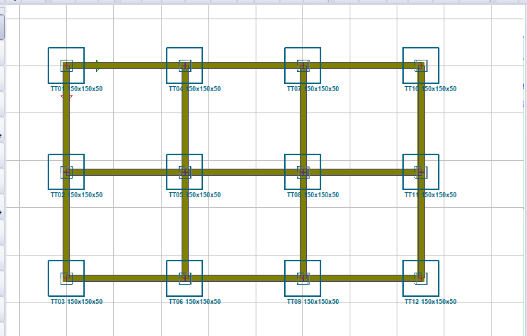
Figure 11 – Tie beams generated by the macro (olive green)
9. Report
Tick the Isolated Footings node in the report tree. The report contains a summary table, a tie beams block and, for each footing, the blocks Inputs (geometry, material, soil, solution type), Combinations and soil pressures (governing and service combinations), Shear and punching, Flexural reinforcement and Result. The report language changes with the program language.
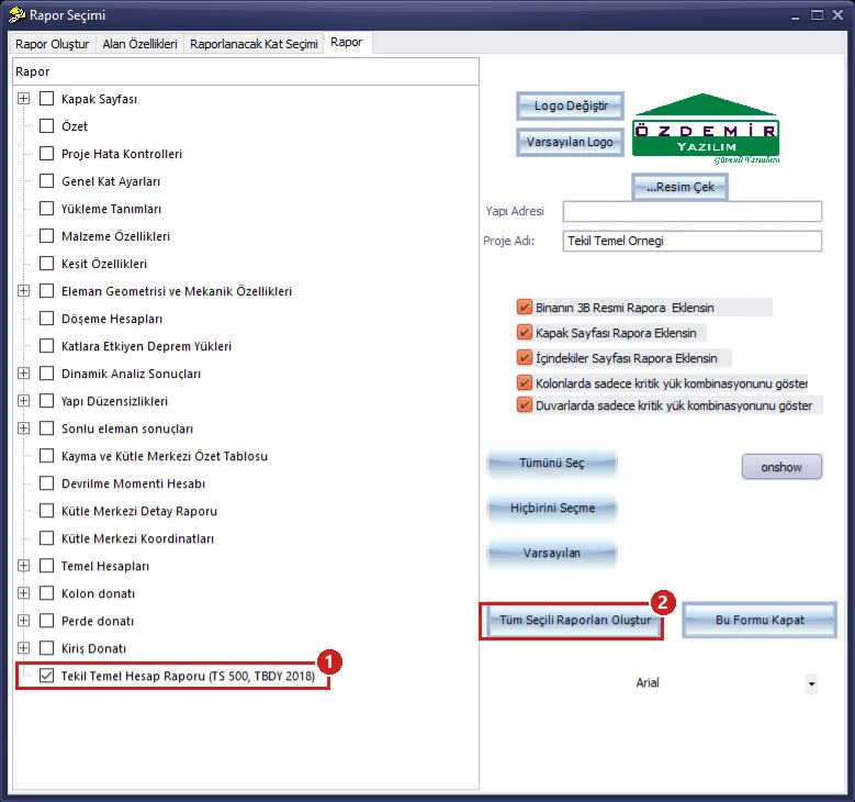
Figure 12 – Report selection: Isolated Footing Calculation Report node (1) and the generate button (2)
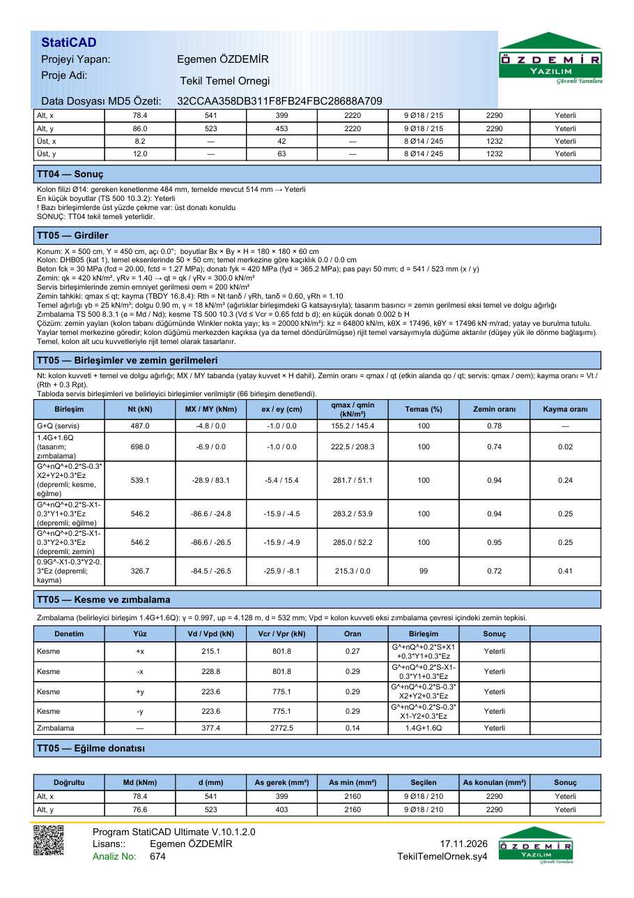
Figure 13 – A footing page from the report: inputs, combinations and soil pressures, shear and punching
10. Drawings and quantity take-off
- Foundation plan: isolated footings, tie beams, names and dimensions (the foundation plan is also drawn in projects with only isolated footings).
- Detail sheet: identical footings grouped into plan and section details, the isolated footing table, the tie beam table, the sheet reinforcement quantity.
- Quantity take-off: ISOLATED FOOTINGS and TIE BEAMS lines (concrete, formwork, blinding concrete), added to the grand totals.
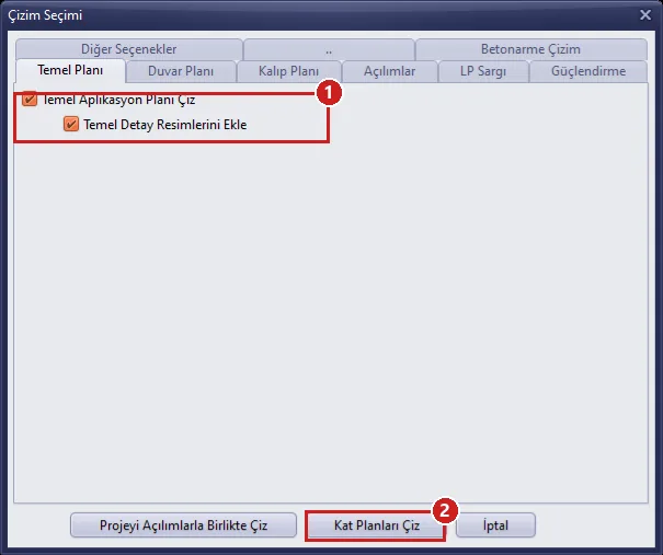
Figure 14 – Drawing Selection, Foundation Plan tab: (1) setting-out plan and details, (2) Draw Storey Plans
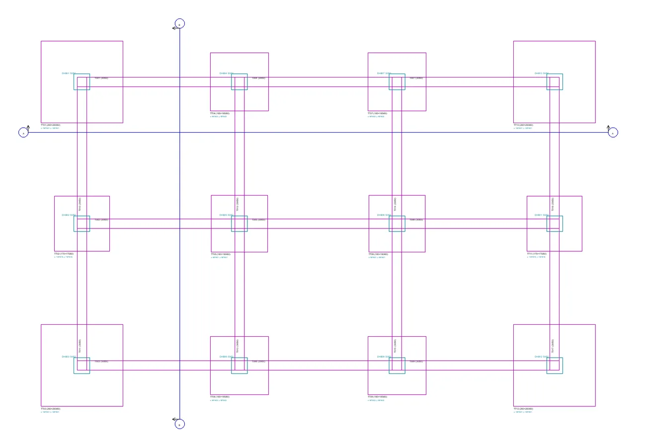
Figure 15 – Foundation setting-out plan
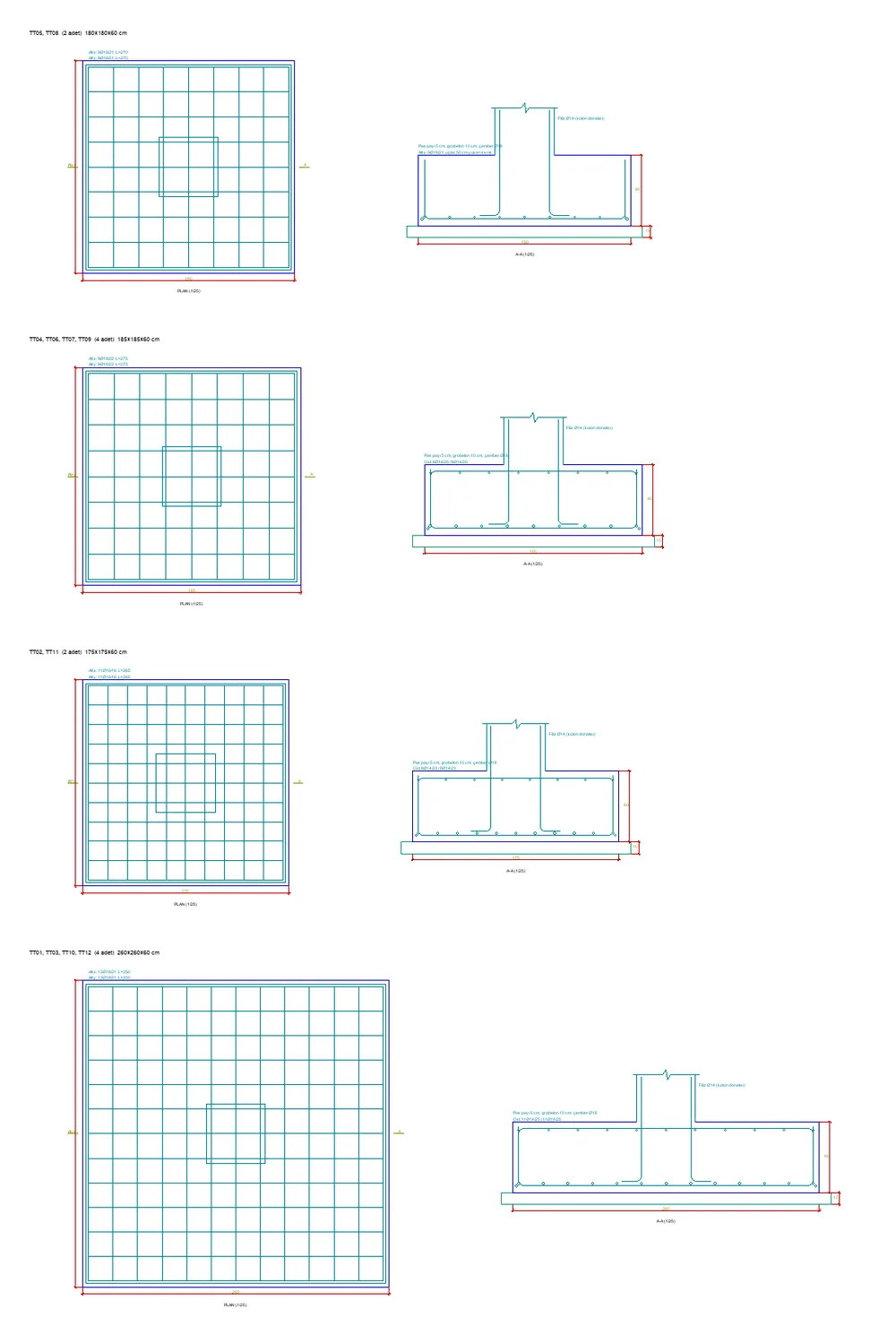
Figure 16 – Detail sheet: identical footings in a single detail (plan and section A-A)
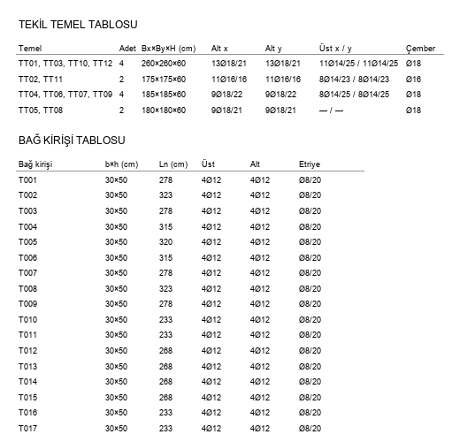
Figure 17 – Isolated footing table and tie beam table
11. 3D view
Isolated footings are drawn as solids in the 3D window; they can be selected by clicking and by window, and the Member Properties and Delete commands apply.
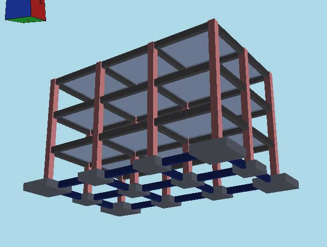
Figure 18 – Isolated footings and tie beams in the 3D solid model (from below)
12. SAP2000 export
A point spring (Uz, Rx, Ry; Ux, Uy, Rz restrained) is written in SAP2000 at the column base of footings with the Y solution. Footings with the S solution are not built as plates in the SAP2000 model; they are transferred with a rigid equivalent spring. K footings are fixed.
When the support type "spring" is selected in the SAP2000 options and the foundation beams (strip footings and tie beams) are transferred, the foundation beam pieces that fall inside the base outline of an isolated footing are split at the outline boundary; the line springs of these pieces are deleted and their end points are connected to the column base point with a rigid body constraint (TTB_<footing name>). In this way the SAP2000 model establishes the same connection as the program's combined structure–foundation analysis model (even if drawn from the column edge). The export log gives, for each footing, the point connected and the number of pieces whose springs were deleted. When the support type "spring" is selected, the supports in the program's model are written at the foundation beam, raft and column base points: horizontal displacements and rotation about the vertical axis restrained, a soil spring in the vertical direction, the two rotations about the horizontal axes free. The soil rotational spring of the foundation beams (Section 14) is added in SAP2000 as point springs, with the influence length, at the frame ends and at points on the frame (column bases, ends of intersecting beams); the SAP2000 frame line spring is translational only.
13. Saving and file compatibility
- Isolated footings, selection group memberships and the project solution type are saved with the project; if there is no isolated footing in the project, this information is not written to the file.
- If a project containing isolated footings is opened in an older program version that does not recognise this feature, the project opens but the isolated footings are not visible; if it is saved in that version, the isolated footings are lost.
14. Assumptions and scope limits
- A footing with a single column, rectangular base and constant thickness. Combined footings and socket footings are outside this scope.
- Footing and backfill weight are taken as uniform pressure in the design (they do not enter the FEM).
- Y and S springs are linear in the global analysis (combinations are the sum of the load cases). In the design the soil does not take tension: in K and Y the rigid footing partial-contact solution, in S the compression-only local plate solution for combinations with uplift.
- There is no horizontal soil spring: horizontal displacements are restrained at the footing base.
- In pushover analysis the column base is fixed.
- In the combined structure–foundation (finite element) analysis option, a project with only isolated footings is also solved: if there is no wall on storey 1 and there is an isolated footing under all first-storey columns, the "Model the foundation" warning is not given; the results are the same as in the classical way. When used together with a strip footing (mixed foundation), the strip footing nodes are restrained horizontally and solved with soil springs vertically; the soil resists rotation of the strip about its own axis with a rotational spring across the strip width (ks·b³/12 per unit length). In a narrow strip this resistance is small: the columns on it behave nearly pinned in the direction perpendicular to the strip, and most of the earthquake shear passes to the columns on isolated footings. The classical foundation calculation, however, takes the strip columns fixed; therefore the analysis gives a warning if the classical calculation is selected in a mixed project. In the example model (a 1 m wide strip footing on one axis, two columns on isolated footings), the share of the earthquake shear of the columns on isolated footings in the direction perpendicular to the strip was 25–50% in the classical calculation and 62–83% in the combined analysis. Tie beams enter the model only in the combined analysis; a tie beam connecting an isolated footing to a strip footing restrains the strip columns against rotation (in the example the share of the columns on isolated footings fell to 53–61%) and brings additional axial force and moment to the footing.
15. Frequently asked questions and troubleshooting
I cannot draw a footing. Make sure you are on the foundation level; Draw → Isolated Footing works only on the foundation level.
The footing does not enter the analysis. If its label says "no column", the footing base does not contain the centre of a first-storey column; move the footing to the column.
The footing is orange. At least one check was not satisfied in the last analysis; look at the analysis warnings and the Result block in the report, try Automatic Sizing.
"Part of the base is uplifting" information in the S solution. These combinations were solved again with the tension springs removed; the results are from this solution. If the contact ratio is low (for example below 50%), enlarge the footing or reduce the moment.
"Mixed foundation" warning. The project has both strip footings and isolated footings, and the classical (rigid assumption) solution is selected in Project General Settings › Foundation Calculation. Because the columns on the strip footing are taken fixed in this solution, the earthquake forces of the isolated footings may remain low. Solve with the "Finite Elements - Combined Structure-Foundation Analysis" option and compare the isolated footing results (Section 14).
"Strip footing or tie beam connected to an isolated footing with the classical solution" warning in the combined analysis. In the classical solution the footing base is fixed, that is, the soil is assumed infinitely rigid; strip footings and tie beams, however, sit on soil springs. The settlement of the strip bends the tie beam and transfers a large moment to the fixed footing. For these footings select the soil springs (Y) or shell (S) solution.
"Compression-only iteration gave no result" warning. In a very small contact region the local solution did not settle to equilibrium; the linear (tension-allowing) field was used in that combination. Enlarge the footing; if the warning continues, compare with the Y or K solution.